How to Build a Pushbutton Circuit with an ATtiny85 Microcontroller
In this project, we show how to build a pushbutton circuit with an ATtiny85 microcontroller.
With the pushbutton, we will be able to give input to the ATtiny85 circuit. When the pushbutton is unpressed, this would represent a logic state of 0 or LOW being fed into the ATtiny. When the pushbutton is pressed, this would represent a logic state of 1 or HIGH being fed into the ATtiny.
Based on whether the pushbutton is pressed or not, we can do anything we want, such as make a device turn on or off. In this circuit, the LED is the output device.
We will make our circuit so that if the pushbutton is unpressed, the LED will be off. If the pushbutton is pressed, the LED will be on.
We can really design 2 types of pushbutton circuits around this. One is that when the pushbutton is pressed, the LED is on only while the button is being pressed down. Sometimes this is what is desired. Other times, it isn't. The other circuit is that when the pushbutton is pressed down and released, the output device, in this case an LED, turns on and stays on. We will show the code for both of these circuits.
This circuit is really a power introductory circuit to embedded microcontrollers because it will illustrate how an ATtiny microcontroller can read input from a digital device to see whether the voltage being fed in is LOW or HIGH.
Then, based on this input value, we can use if statements to decide what action the microcontroller should take if the input is read as either LOW or HIGH.
We show how to build this circuit below.
Components Needed
- ATtiny85 microcontroller
- Pushbutton
- LED
- 470Ω Resistor
The ATtiny85 microcontroller can be obtained through many electronic online retailers. One easy place to purchase it is ebay. Depending on where you get and the quantity you get, it can range anywhere from a little over $1-$4.
The datasheet for the ATtiny85 microcontroller is shown at the following link: ATtiny85 Datasheet.
The ATtiny85 chip is an 8-pin microcontroller.
The pinout of the ATtiny85 is shown below.
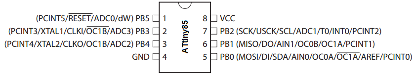
The power pins are VCC and GND, pins 8 and 4. Anywhere from 1.8V to 5.5V can power the ATtiny85 chip. To our circuit, we will simply apply 5V to VCC and connect GND to power ground.
Besides the 2 power pins discussed right above, the other 6 pins of the ATtiny8 are I/O pins labeled as PORTB pins. These are labeled on the datasheet and in the pinout above as PB0 to PB5.
These pins can be used as inputs or outputs, and they have various uses depending on what you need the pin for.
In our circuit, we are using pin 1, which is PB5, as an input and using pin 5, which is PB0, as an output. Pin 1 is
The PORTB pins of the ATtiny85 source power, so when connecting a digital output, the port provides positive power to the output device, so that we just need to connect the other end of the device to ground.
ATtiny85 Pushbutton Circuit
The circuit diagram of the pushbutton circuit we will building with an ATtiny85 microcontroller is shown below.

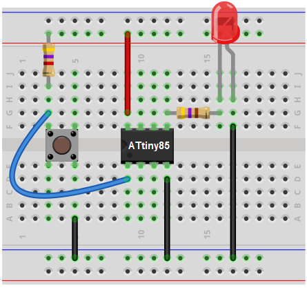
The breadboard schematic of the circuit above is shown below.
 >
>
First, we give power to the ATtiny85 chip. This is done by connecting 5V to VCC, pin 8, and by connecting GND, pin 4, to ground.
Next, we attach to the output of the ATtiny85 microcontroller an LED. This LED will be attached to the pin PB0. Being that the output sources current, the anode of the LED connects directly to the output pin and the cathode connects to ground.
The pushbutton is attached to pin PB5. One terminal of the pushbutton connects to ground and the other terminal is connected to +5V of power via a 4.7KΩ pull-up resistor. The side of the terminal connected to the +5v terminal side connects to pin PB5.
When the pushbutton is unpressed, not pressed, the pin is HIGH. This is because this side is connected to +5V of power. Being that the pushbutton forms an open circuit when it is unpressed, all the voltage falls across the resistor. Therefore, the whole voltage of the power supply falls across the resistor. Therefore, when unpressed, the voltage at pin PB5 is +5V.
Now when the pushbutton is pressed down, the electrical pathway is closed all the way from +5V to ground. Now all of the voltage is not concentrated across the resistor and the voltage at pin PB5 drops drastically. So the voltage at PB5 is now LOW.
And this completes all the circuit connections needed for the ATtiny85 pushbutton circuit.
Now all we need is the code.
Code
The code needed in order to turn on the LED
when the pushbutton is pressed down is shown below.
#include <avr/io.h>
int main(void)
{
while(1)
{
DDRB= 0b00111110;
int pushbutton= PINB5;
if (pushbutton == 0){
PORTB= 0b00000001;
}
else
{
PORTB= 0b00000000;
}
}
}
First, we must important the <avr/io.h> library.
Then we create the main loop() which will house the while(1) loop. This loop is an infinite loop. So the program will keep executing the code contained inside of it infinitely, over and over again. In this loop, we declare the DDRB pin as 0xff, which makes all of the I/O pins of the ATtiny85 outputs.
In the next line, DDRB= 0b00111110;, we set all the outputs HIGH, except for PBO. PB0 is the only pin that is set as an input. Remember that the ATtiny85 chip has 6 I/O pins. So the first 2 numbers after b are irrelevant, since they would represent the 7th and 8th I/O pins.
The next line declares an integer named pushbutton. This variable is equal to PINB5, which represents the input to pin PB5. Being that pin PB5 is normally HIGH via the pull-up resistor to 5V, if it goes LOW, this indicates that the pushbutton has been pressed.
So we create an if statement that if the variable pushbutton is equal to 0, PORTB=0b00000001, which means that the LED attached to PB0 turns on. Else, PORTB= 0b00000000, which means that all the outputs are off, including the LED attached to pin PB0.
The LED will be on only while the pushbutton is pressed down, for the code shown above.
If you want the LED to be permanently on once the pushbutton is pressed down once, it would require manipulating the code. This code will be placed here as soon as it's created.
The loop then starts again, checking to see if there is any new value to the input of PB5.
And this is how digital input can be read by
an ATtiny85 microcontroller.
Related Resources
How to Build an LED Circuit with an ATtiny85 Microcontroller
How to Biuld a Traffic Light circuit with an ATtiny85 Microcontroller