
Arduino Ammeter Circuit
In this project, we will show how to connect an analog current panel meter to an arduino, so that we can measure and display the amount of current flowing into the arduino board.
This circuit, then, essentially function as an ammeter, which is a device that measures current.
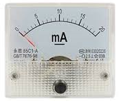
The analog panel we will use is a current panel, meaning it is designed to measure current. It is calibrated in milliamperes (mA), going from 0ma to 20mA, meaning it can measure anywhere between 0mA to 20mA.
Being that we are dealing with electronics, this is a current range in which many electronic circuits operate. Many electronic components such as LEDs run off of about 15-20mA. However, if you need a different or wider range of values, there are several other types of panel meters available that are calibrated to measure different ranges. In this circuit, though, we are using a panel meter that can measure 0-20mA of
In order to perfectly demonstrate how this circuit works, we will connect a potentiometer to the 5V supply of the arduino. When the potentiometer is turned so that its resistance is nearly 0Ω, the voltage will be at around 0V. When the potentiometer is midway between 0V and its rated resistance, the voltage will be at about 2.5V. When the potentiometer is turned all the way so that its resistance is at its rated resistance (highest resistance level), the voltage will be at the full 5V that the arduino pin offers.
This is a great way to demonstrate how a current panel meter can coexist with an arduino.
We must calibrate our circuit so that the input and output levels are proportionate to one another. To decide on calibration measures,
we use both hardware and software
configuration. Depending on the amount of current the meter deflects full scale for determines the resistor value we will choose. This will be explained below.
Components Needed for Arduino Ammeter Circuit
- Analog Current Panel Meter
- 200Ω Resistor
- Cermet Potentiometer
- Arduino
The analog current panel meter we will be using in this circuit from a Chinese manufacturer and is part of a series called the 91 panel meter series. It can be obtained from Sparkfun at the following link:Sparkfun- Analog 20mA Current Panel Meter It can measure up to 20mA of DC current with 5% accuracy.
Cermet potentiometers are really the easiest type of potentiometers for connection to a breadboard and their connection to the circuit is explained
in detail in this circuit building project. However, if you are accustomed to another type of potentiometer and know how to use it, use it. It will work the same
as a cermet. As far as the value for the potentiometer, it really doesn't matter. Any value will suffice, whether 1KΩ, 10KΩ, 100KΩ, etc.
Arduino Ammeter Circuit Schematic
The arduino ammeter circuit we will build is shown below.
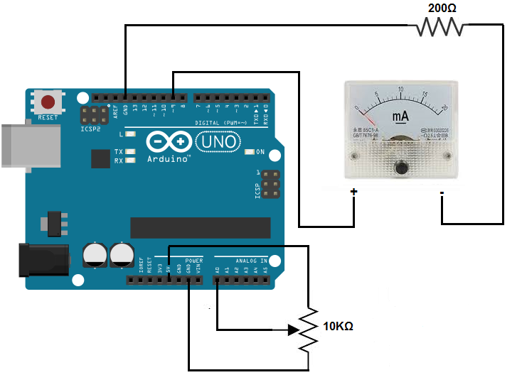
We place a 200Ω resistor in series with the analog current panel meter as a kind of "calibrating resistor." Since our current panel is measuring milliamperes and internal resistance isn't built in, it needs some external resistance in order to limit current flow. With a 200Ω resistor and 5V applied to the panel meter, the panel meter will deflect to a full current of 20mA. Without the external resistor, the panel meter would deflect a full current of 20mA with very little voltage; thus, it wouldn't be very useful. Since an arduion can output as much as 5 volts of power, we calibrate so that only when there is 5V will the panel meter give a full current reading of 20mA.
Other than that, we connect a potentiometer to the analog input of the circuit. The value of the potentiometer really doesn't matter, but in this circuit, a 10KΩ potentiometer is used. To connect the potentiometer, we must be carefully to connect all the leads properly to the arduino. For a cermet potentiometer, pick up the potentiometer so that the wiper terminal is left most. Now turn the potentiometer knob all the way counterclockwise. It should be that the resistance between the end terminal farthest from you and wiper terminal be near the rated resistance of the potentiometer. So if you use a 10KΩ potentiometer, the resistance should be almost 10KΩ. Connect the end terminal farthest from you to the 5V terminal of the arduino and connect the other end terminal (which would be closest to you) to GND on the arduino board. Connect the wiper terminal of the potentiometer to A0 on the arduino board.
When initally turned on, the resistance that the potentiometer offers is at its greatest value, so the current will be very low, almost 0mA. However, as you turn the knob clockwise, the resistance lowers so that the current keeps increasing. When the potentiometer is turned all the clockwise, the resistance it offers is almost 0Ω. Therefore, current flow will be greatest and will deflect full scale to 20mA.
This ammeter circuit works on Ohm's law. Current is equal to voltage divided by resistance (I=V/R). So that when resistance is high, current is low.
And when resistance is low, current is high. This is the principle this circuit exploits.
Code
Now that we have our circuit schematic setup, the only thing we now need is our code so that the arduino will know to process the voltage that falls across the potentiometer, which is connected to analog pin A0, and then correspondingly allow for deflections of the panel meter.
The full code is shown below.
const int analogInPin= 0;
const int analogMeterPin= 9;
int sensorValue= 0;
int outputValue= 0;
void setup ()
{
//nothing in setup
}
void loop()
{
sensorValue= analogRead(analogInPin);
outputValue= map (sensorValue, 0, 1023, 0, 255);
analogWrite (analogMeterPin, outputValue);
}
Since the potentiometer wiper terminal is connected to analog pin A0, we initialize the constant analogInPin to 0. Since one terminal of the panel meter is connected to D9, we initialize the variable analogMeterPin to 9.
We later create a variable sensorValue which will hold the value of the current that flows across
the potentiometer and another variable outputValue which takes the sensorValue, which can range from 0 to 1023,
and converts it into an analog value that ranges from 0 to 255. Once we have this converted value, we then can write this
value to the analog panel meter, which is connected to D9. This allows the meter to shift correspondingly with the
current flowing through analog pin A0.
To see how this circuit works when actually connected together, see the video below.
Related Resources
How to Build a Voltmeter Circuit with an Arduino
How to Drive a 7 Segment LED Display with an Arduno