
Arduino Voltmeter Circuit
In this project, we will go over how to connect an analog volt panel meter to an arduino so that it can measure and give us a readout on voltage through the panel.
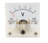
The analog panel we will use is a volt panel, so it is designed to measure voltage. It is calibrated in volts, going from 0V to 5V, meaning it can measure anywhere between 0V and 5V.
There are other types of panels that are designed to measure current. These are called ammeters and are calibrated in either milliamperes (mA) or amperes (A).
But again, for this circuit, we are measuring voltage, so we are using a volt panel.
This type of circuit can give us any type of voltage readout for any type of circuit we may deal with. So, in essence, the circuit functions as a voltmeter, a device that measures and displays voltage.
The voltmeter panel doesn't need any calibration in hardware. One end of its terminal connects to D9 of the arduino board and the other ends connect to Ground (GND).
In order to perfectly demonstrate how this circuit works, we will connect a potentiometer to the 5V power terminal of the arduino. When the potentiometer is turned so that its resistance is nearly 0Ω, the voltage will be at around 0V. When the potentiometer is midway between 0V and its rated resistance, the voltage will be at about 2.5V. When the potentiometer is turned all the way so that its resistance is at its rated resistance (highest resistance level), the voltage will be at the full 5V that the arduino pin offers.
This is a great way to demonstrate how a volt panel meter can coexist with an arduino.
Components Needed for the Voltmeter Circuit
- Analog Panel Meter
- Cermet Potentiometer
- Arduino
The analog panel volt meter we will use can be found at Sparkfun here: Analog Panel Meter- 0-5VDC. This can measure from 0V to 5V of DC voltage with 2.5% accuracy. It's fairly accurate. When tested with a DC power supply, the corresponding DC voltages were pretty much dead-on with what it should be.
Cermet potentiometers are really the easiest potentiometers to use for breadboard connections. And how to connect them is detailed here in this
circuit building project. But if you're used to using another type, go right ahead. Any potentiometer will work. As far as the value goes, really, any
value potentiometer can be used for this circuit. The value does not matter. You can use simply whatever value potentiometer you have whether it's
a 1KΩ, 10KΩ, 100KΩ, etc. All will work, as long as they are connected properly. When at 0Ω, the volt panel should display 0V. When at the midway, the panel needle
should swing to about 2.5V. When turned to its rated resistance, the panel needle should swing to about 5V.
Arduino Voltmeter Circuit Schematic
The arduino voltmeter circuit we will build is shown below.
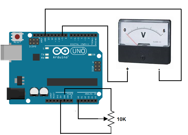
The circuit connections are pretty straightforward and basic.
When connecting the analog volt panel meter to the arduino, we connect one terminal to D9 of the arduino and the other terminal to ground (GND).
When connecting the potentiometer, we need to be careful how we are connecting it. For a cermet potentiometer, pick up the potentiometer and orient it so that the wiper terminal is the terminal to the most left. Now turn the knob so that it is turned all the way counterclockwise. It should now be that the resistance between the wiper terminal and the end terminal closest to you be almost 0Ω. Now connect the end terminal that is nearest to you to the 5V terminal of the arduino and connect the other end terminal to GND of the arduino. The wiper terminal connects to A0 of the arduino. This setup allows the arduino to read the voltage input into it according to the resistance offered by the potentiometer. Since the potentiometer is turned so that the resistance is almost 0Ω initially, at first the analog panel meter will read 0V. As you turn the knob of the potentiometer clockwise, the voltage displayed by the panel meter will increase until it is at its full scale 5V reading.
This is all a principle of Ohm's law. With low resistance, there will be very low voltage, since voltage= current * resistance.
With increasing resistance, the voltage output will be increased.
When the potentiometer is at its maximum value, the volt panel should reflect the maximum voltage value of 5V.
Code
Now that we have our circuit schematic setup, the only thing we now need is our code so that the arduino will know to process the voltage that falls across the potentiometer, which is connected to analog pin A0, and then correspondingly allow for deflections of the panel meter.
The full code is shown below.
const int analogInPin= 0;
const int analogMeterPin= 9;
int sensorValue= 0;
int outputValue= 0;
void setup ()
{
//nothing in setup
}
void loop()
{
sensorValue= analogRead(analogInPin);
outputValue= map (sensorValue, 0, 1023, 0, 255);
analogWrite (analogMeterPin, outputValue);
}
Since the potentiometer wiper terminal is connected to analog pin A0, we initialize the constant analogInPin to 0. Since one terminal of the panel meter is connected to D9, we initialize the variable analogMeterPin to 9.
We later create a variable sensorValue which will hold the value of the voltage that falls across
the potentiometer and another variable outputValue which takes the sensorValue, which can range from 0 to 1023,
and converts it into an analog value that ranges from 0 to 255. Once we have this converted value, we then can write this
value to the analog panel meter, which is connected to D9. This allows the meter to shift correspondingly with the
voltage drops across analog pin A0.
To see how this circuit works when actually connected together, see the video below.
Related Resources
How to Build an Ammeter Circuit with an Arduino
How to Drive a 7 Segment LED Display with an Arduno