
How to Build an Astable Multivibrator Circuit with a 4049 Inverter Gate Chip
In this circuit, we will show how to build an astable multivibrator circuit using a 4049 inverter gate chip along with a capacitor and resistor.
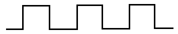
By definition, an astable circuit is that one that oscillates between 2 states, HIGH and LOW, over and over and over again, indefinitely. It never holds one state. It constantly cycles from HIGH to LOW, HIGH to LOW, repeatedly. Therefore, it produces a square waveform signal as output or closely resembles it.
So this circuit functions as an astable multivibrator. It's constantly going from ON to OFF, ON to OFF, repeatedly. An astable multivibrator is a multivibrator which has no stable state, so it's constantly switching from ON to OFF, indefinitely.
Astable circuits are very good and useful when you want to flash a device on and off, on and off, repeatedly, just like how a train sign crossing would be when it alternates with the lights. So astable circuits are very useful if you want a device turning on and off. Most of the times, it serves as warnings for something.
In this circuit, we will flash on an output device, an LED, on and off. This is the essence of astable multivibrator functioning.
Flashing LEDs are used in many types of electronic devices, including in cars, dashboards, printers, fax machines.
It can be used basically for any circuit in which you want a device turning on and off at repeatable intervals.
We will show how to build this circuit below. And we will show how we can modify the values of the capacitor and resistor to increase or decrease the flashing rate.
Components Needed
- 4049 Inverter Gate Chip
- 10KΩ resistor
- 100µF electrolytic capacitor
- LED
- Second LED (optional)
- 470Ω resistors
The 4049 hex inveter gate chip can be obtained very cheaply from a number of online retailers for just a few cents. One place it can be obtained from is Tayda Electronics at the following link: Tayda Electronics- 4049 Hex Inveter Gate IC. However, it is a very popular chip and many electronics parts suppliers have them.
The pinout of the 4049 is shown below, so that you can see how to
connect it in the circuit.
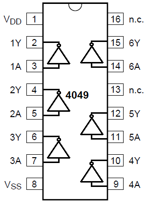
This inverter has 6 independent inverter gates.
The pins marked with A's are the inputs to the inverter gates and the pins marked with Y's are the outputs of the inverter gates.
The following chart shows inverter gate logic, which shows what output a
inverter gate chip will produce for a given input.
| Inverter Truth Table | |
| Input | Output |
| L | H |
| H | L |
This means that if the input is 0, the output will be 1 or HIGH. If the input is 1 or HIGH, the output will be 1 or LOW.
We will use this inverter logic as the basis for the function of our circuit.
Any voltage below 1/2 the supply voltage will be interpreted as a 0. And any voltage greater than 1/2 of the supply voltage will be interpreted as a 1.
As far as the other components is concerned, the resistor and capacitor values aren't set in stone. The resistor and capacitor values of 10KΩ and 100µF are chosen so that it causes the LED to blink once a second. But you can choose any value, especially ones that are higher. It isn't recommended to choose lower values for them because then the rate of flashing will be so fast, it may not de detectable by the human eye. Therefore, 1 second should be seen as near the low end of the range for the frequency and shouldn't get much lower.
470Ω resistors are used as current-limiting resistors for the LEDs so that they don't get blown out.
Also, a second LED is optional because this circuit can be modified to have 2 LEDs flashing alternatively like railway lights. We will show to connect this down below.
Astable Multivibrator Circuit with a 4049 Inverter Gate Chip
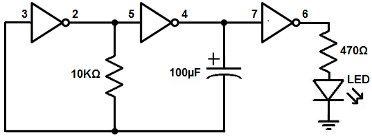
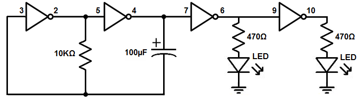
The astable multivibrator circuit we will build with
a 4049 inverter gate chip is shown below.
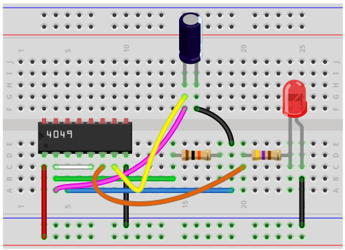
The breadboard circuit of the circuit above is shown below.
So in order to power on the chip, we provide about 5V to VDD, pin 14, and connect VSS, pin 7, to ground. This establishes sufficient power for the chip and for our load, which is an LED, to operate.
For this circuit, we use 3 of the 6 inverter gates from the 4046 chip. Later on, we modify the circuit to use 4 of the 6 when adding a second LED.
The circuit works on the basis of feedback. The capacitor is connected to the input of the first inverter gate.
So let's have the capacitor as the starting point of the circuit, because the capacitor is the focal point of it and is the most crucial element that allows for the astable capability.
When the circuit is turned on, the capacitor slowly charges up. It charges up and up and up. Once it hits the halfway point of the supply voltage, the capacitor discharges its charge. When the capacitor discharges its charge, it is a LOW logic state. Therefore, the first inverter outputs a HIGH input and the second inverter outputs a LOW output, since it inverts the first signal. When the capacitor charges up again to midway of the supply voltage or a little above, it goes to a HIGH state. This HIGH state feeds into the first inverter and becomes a LOW. This LOw state feeds into the second inverter and becomes a HIGH. It is the constant charging and discharging of the capacitor that changes the state frequently of the outputs of the inverters.
Since the resistor is in between the 2 inverters, it's right in the midst of the action. Since the output of the first inverter is constantly switching due to the charging and discharging of the capacitor, if you measured the voltage across the resistor, it would be constantly channeling from high to low voltage over and over again.
So the capacitor is the heart of the circuit that creates and allows for the switching action. With the resistor, they form an RC network that determines the speed at which the output device turns on and off.
One thing, you cannot simply attach your output to the capacitor. The capacitor is very unstable as it is, constantly switching voltage. If you attach an output either in series or in parallel with it, it most likely won't work.
The best thing to do is to buffer the output voltage of the capacitor. This gives a high impedance path for the voltage and stabilizes the output voltage from the capacitor. Then to the output of the buffer, you attach the output device that you want to flash on and off.
Since the inverter is a buffer (it's an inverting buffer), to buffer the output, we simply use an additional gate on the chip. This buffers the capacitor output. So we place the capacitor voltage on the input of a third inverter gate and to the output of that gate, we place our LED along with a current-limiting resistor to limit current going to the LED.
So this circuit actually works really well.
The rate at which the output device flashes is determined by the value of the resistor and capacitor. The resistor and capacitor flash at a rate equivalent to the formula, τ=RC. Since, in this circuit, we are using a 10KΩ resistor and a 100µF capacitor, this creates a time constant of τ=RC= (10KΩ)(100µF)= 1s. Therefore, the LED will flash on every second.
If you want to increase the frequency of the circuit, which is to make the time constant longer, you either increase the value of the capacitance or resistance or both. So, for example, if we changed the resistor to a 100KΩ resistor, while keeping the capacitor value unchanged, the LED would flash on every 10 seconds.
If you want to decrease the frequency of the circuit, which is to make the time constant shorter, you either decrease the capacitance or resistance or both. But keep in mind that if you decrease the frequency too much, the human eye may not be able to detect the change due to its speed. Therefore, it will just seem like the LED is permanently on. It switches so fast that the eye won't be able to detect when it's off. This is why using resistor and capacitor values that are too low are counterproductive for the sake of this circuit. You can lower it a little but if you do too much, it will seem as if it's not astable and it's just permanently connected on. So be aware of this.
So this circuit actually works really well for astable operation.
Like many circuits, we can make modifications for it to perform other actions. For example, if we take the output of the third inverter, which is the inverter that has our output LED, and feed this output into the input of a fourth inverter, we invert this output signal. If we add an LED to the output of this fourth inverter, the LEDs will now alternate in flashing. This is because the fourth is operating to the inverted signal of the other LED. Therefore, when one LED is on, the other is off and vice versa. They rotate. Therefore, you aget alternating flashing LEDs.
To see the schematic diagram of this circuit, see
Astable Multivibrator with a 4049 inverter chip with multiple outputs.
And this is how an astable multivibrator circuit can be built with a 4049 inverter gate chip.
To see how this circuit operates in real life, see the video shown below.
Related Resources
How to Build a Multivibrator Circuit with a 4047 chip (for astable mode operation)
How to Build an Astable Multivibrator Circuit with a 4011 NAND Gate Chip