How to Build a Common Anode RGB LED Circuit
In this project, we are going to build and operate an RGB LED circuit using manual switches.
An RGB LED is an LED that can light up either red, green, or blue.
The type of RGB LED we will use in this circuit is a common anode RGB LED. This is an LED in which all the anodes, or positive voltage terminals, of the LEDs are tied together common.
Depending on which anode gets +3V determines which color the LED lights as.
The RGB LED is a dynamic LED because of the fact that it can light up to many different colors. Therefore, if you need multiple colors to be shown and if you have very limited space on a board (where you can't fit 3 separate LEDs), an RGB LED works perfectly.
In this circuit, we will use toggle switches to control the RGB LED. We can turn on one toggle switch at a time, 2 at a time, or all 3 at a
time. If we turn on one, only that color will light up. If we turn on multiple LEDs, all the selected LEDs will turn on.
Components Needed
- Common anode RGB LED
- 3 220Ω resistors
- 3 toggle switches
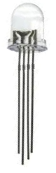
The RGB LED is a 4-pin LED.
For the common anode RBG LED, one pin is power (pin 2) and the other 3 pins are the cathodes of the red, green, and blue LED.
The pinout of the common anode RGB LED is shown below.
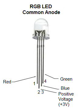
The RGB LED we are using is a common anode LED. This means that all the anodes of the LED are tied together, i.e. they are common. We have to connect all of the cathodes of the LEDs to ground in order for the LEDs to work.
The diagram at the following link shows the internal layout of the RGB LED:
Internal Diagram of a Common Anode RGB.
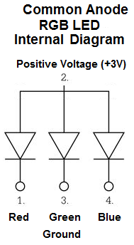
So with common anode RGB LEDs, we connect pin 2 to +3V of power. This powers all of the LEDs. And then we connect all of the toggle
switches to positive voltage and ground, so that we can turn off or on whichever LED. When the switch is flipped to the ground terminal side, the LED
turns on. When switched to the +3V terminal side, the LED turns off.
Common Cathode RGB LED Circuit
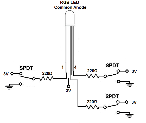
The common anode RGB LED circuit we will build with manual switches is shown below.
This above circuit built on a breadboard is shown below.
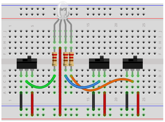
The connections are pretty simple.
We connect the power pin pin (pin 2) of the RGB LED to +3V of power. This gives +3V of power to each of the anodes of the 3 LEDs.
We then connect toggle switches to each of the other pins, which are the cathodes of each of the 3 LEDs.
To connect the toggle switches, we ground one of the terminal pins through a 220Ω resistor. We connect the other terminal pin to the positive voltage source. We then connect the middle pin to the cathodes of each of the LEDs. This allows us to flip the LED on or off.
How the circuit operates is that when we turn the toggle switch to the ground end of the toggle switch terminal, the LED connected to that switch will turn on. This is because the power pin is already at +3V (pin 2). When the toggle switch is flipped to ground, there is a potential difference and current can flow. When the toggle switch is flipped to the +3V end, both ends are at +3V and there is no electrical difference. Therefore, no current can flow, and the LED is off.
We can have all LEDs off, in which case the RGB LED does not light up at all.
Or we can turn on one LED at a time, in which case that color alone will show, whether it's red, green, or blue.
Or we can turn on any combination, 2 at a time, all 3 on at once.
When we turn on multiple LEDs, the colors that are on will show.
And this is how a common anode RGB LED works.
Related Resources
How to Build a Common Cathode RGB LED Circuit