
How to Build a Continuity Tester Circuit
In this circuit, we will build a very simple continuity tester, actually one of the simplest that can be built.
A continuity tester is a device that checks for continuity along a device to see if the device is electrically intact.
If the device is electrically continuous, there are no breaks in the device and current can flow through it. It functions as a closed circuit.
If the device is not electrically continuous, there are breaks in the device and current cannot flow through it.
Electrical continuity can be checked on all types of devices such as alligator clips, all types of wires, and electrical connectors. It can basically be checked on any device that has low resistance.
In our circuit, we will build a simple LED circuit, leaving space so that we can detect the component we want to check for continuity. If the device is continuous, then the LED will light up. If the device is not continuous, the LED will not light up.
This is probably the simplest continuity tester that can be built.
Components Needed
- 470Ω resistor
- LED
- Alligator Clips
- Power source
The All we need for this circuit is very basic components of an LED, a resistor to limit current ot the LED,
and alligator clips. We also need a power supply or batteries to supply the voltage necessary to light the LED.
Continuity Tester Circuit
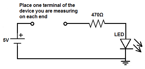
The continuity tester we will build that lights up an LED when there is continuity is shown below.
The breadboard schematic of the circuit above is shown below.
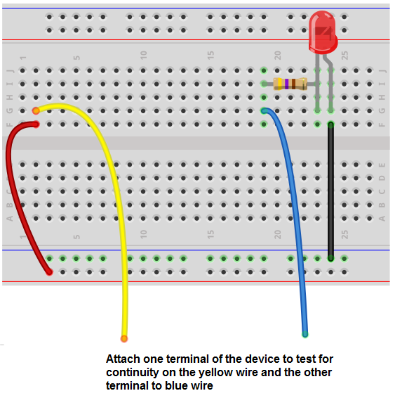
As can be seen, this circuit is very basic.
First, we need a power source. You can use anywhere from 3V-5V to power this circuit.
We then can put either a wire or an alligator wire in series with the positive voltage line of the power source. We then skip a place on the breadboard and put another wire (or alligator
wire) and connect a 470Ω resistor and an LED in series. The 470Ω resistor is to limit current going to the LED so it doesn't blow out. Without the resistor, the LED will most likely blow.
How the Circuit Works
We have 2 wires or alligator clips coming out of the circuit.
The component we want to check for continuity gets attached to these 2 wires in the circuit.
For example, we can check wires for continuity. We can check alligator clips. Any electrical connector that has 2 ends can be checked for continuity. Any basic breadboard wiring component.
How this circuit works is if when we connect the component to the 2 wires in the circuits and the LED lights up, this signals that there is continuity in that component. If it the LED doesn't light up, there is no continuity in that component; in other words, there is a break in that component and it should be discarded.
How this all works is the a very basic concept of current flow. If the component is continuous, current can flow through and, in this case, power on the load. It simulates a closed circuit. So current can flow through. However, if the component is not continuous, meaning it has a break, then no current can flow across to power on the load. This is why the LED does not turn on. It stimulates an open circuit. In an open circuit, no current can flow through because it's a broken path.
In most multimeters, in continuity mode, the multimeter will beep to signal continuity. For that, all you have to do is make a simple switch to this circuit. Increase the voltage to the level that is necessary to power on the buzzer and remove the 470Ω resistor. Buzzers don't need resistors. In fact, they lower the sound drastically that buzzers can emit. And then you'll have a continuity that beeps, just like a professional commercial multimeter, when continuity is detected.
So this is pretty much the simplest type of continuity tester that we can build.
Related Resources
How to Vary the Brightness of an LED
How to Build an LED Driver Circuit
How to Build an LED Flasher Circuit