
How to Build a Current Source Circuit
In this project, we will show how to build a very accurate current source circuit which is a reliable current source with less than 1 percent error.
A current source circuit is a circuit which can output a stable, steady current, without fluctuating much.
So, for example, we may want a steady source of 10mA, in that case we need a current source of 10mA.
There are many reasons to want a steady flow of current. It may be for accuracy where a different current may cause some loss of precision. It may be component protection, in which too little current and the circuit doesn't work or too much current and circuit components are damaged.
So there are many various reasons why a current source may be needed and used.
In this circuit, we use an op amp and a MOSFET transistor to create our current source.
This MOSFET op amp circuit is more reliable than a simple bipolar transistor-driven source. The amount of leakage current is extremely small.
So, again, we're going to put together a current source circuit that's very reliable to less than a 1% error.
We'll also show a variation you can do to make this current source adjustable to adjust to the output current
you desire.
Components Needed
- LM741 Operational Amplifier
- LND150 N-Channel Depletion-type MOSFET
- 1KΩ resistor
- A load such as an LED
- Potentiometer (optional)
The LM741 is an operational amplifier IC that we will use as the op amp. It contains a single op amp .
The chip has 8 pins in total. The pinout is shown below.
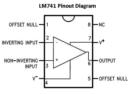
If you want a complete understanding of what each pin is and what each pin does, see LM741 Op Amp- Pinout.
The only pins we will use for our comparator circuit are 5 of the pins, V+, V-, inverting input, noninverting input, and output.
To power the chip, we apply positive voltage to V+, pin 7, and we ground V-, pin 4.
The inverting and noninverting terminals are the 2 input terminals of the op amp. We connect our inputs of the op amp to these terminals.
The output of the op amp is pin 6.
So that's all the information required to connect the op amp of the LM741.
The other major component is the MOSFET.
The type of MOSFET that is used is an N-channel, depletion-type MOSFET.
By N-channel, it is just meant how the MOSFET is internally doped. If it is N-channel, for the circuit to work, positive voltage must be applied to the drain of the MOSFET. If it were P-channel, negative voltage would be applied.
By depletion-type MOSFET, it is a type of MOSFET that is normally on.
Depletion-type MOSFETS are MOSFETs that are normally on. When you connect a depletion-type MOSFET, current flows from drain to source without any gate voltage applied. This is why it is called a normally on device. There is current flow even without a gate voltage. With a depletion-type MOSFET, maximum current flows from drain to source when no difference in voltage exists between the gate and source terminals (VGS=0).
However, if a voltage is applied to the gate lead of the MOSFET, the drain-source channel becomes more resistive. As the gate-source voltage increases more and more, the current flowing from drain to source decreases more and more, until all current flow from drain to source ceases.
So this is how this type of MOSFET works.
There are several type of N-channel, depletion-type MOSFETs available, but the LND150 is a very cheap one that works very well. If you are using a high amount of power, then it would be best to get a power MOSFET.
The datasheet for the LND150 MOSFET is shown at the following link: LND150 N-channel Depletion-type MOSFET.
Remember that for whichever N-channel depletion-type MOSFET you use, make sure you observe the terminals on the datasheet to know which terminals
are which for the gate, source and drain.
Different MOSFETs are different and may have terminals in different positions. So just make sure to check, or else the circuit may not work properly.
Current Source Circuit
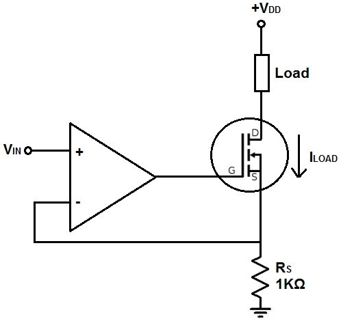
The current source circuit that we will build with an op amp and MOSFET is shown below.
The breadboard circuit of the circuit above is shown below.
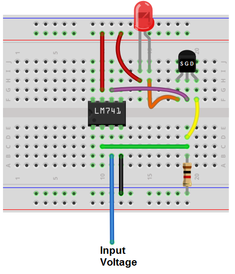
The first thing we should do is to give power to the circuit, so that it can operate.
To power the LM741 op amp, we apply positive voltage to V+, pin 7, of the op amp. We ground, V-, pin 4, of the op amp. This establishes power to the op amp. You can use about +5V to power the LM741.
For this circuit, we need 2 other sources of power.
We need to connect power to the source of the drain of the MOSFET so that it can power on a load, which in this case in an LED. So we connect positive voltage to the anode of the LED and connect the cathode of the LED to the drain of the MOSFET. This allows for sufficient power to the load of the MOSFET. For an LED, this can be about 5V. If it were a device that requires more power, such as a DC motor, then you would need greater voltage. But for an LED, 5V is sufficient.
The last source of power we need is for the input voltage to the noninverting terminal of the op amp. You can make again 5V if you want, or you can vary it.
So these establish all the voltage sources necessary for the circuit.
So we'll now go through how it works.
The inverting input of the op amp samples the voltage across resistor RS and then compares it with the voltage applied to the noinverting input.
This op amp circuit is basically wired to function as a voltage follower. A voltage follower is a circuit in which the output voltage is the same as the input voltage. It's called a voltage follower because the output voltage follows, or mimics, the input voltage.
When the noninverting terminal receives an input voltage and the inverting terminal is connected to the output of the op amp, this is the setup of a voltage follower. When the circuit is connected as a voltage follower, the output voltage resists changes unless the input voltage changes. So if the input voltage is steady at a certain value, the output voltage does everything possible to maintain the same voltage as the input. It strongly resists urges to voltage change. Therefore, if the load current going through the drain and source of the transistor changes, the voltage output by the op amp changes to adjust for this change in current, so that the output voltage (voltage across the resistor RS) is constant, which ends up bringing the load current back to its baseline value. Since the output of the op amp is connected to the gate of the MOSFET, the voltage at the gate of the MOSFET changes if there are changes in the load current. If there is an increase in load current, the op amp outputs a higher voltage (remember this is a depletion-type MOSFET). This, in turn, lowers the current so that it goes back to its baseline value. If there is a decrease in load current, the op amp outputs a lower voltage. This, in turns, increases the current so that it goes back to its baseline value.
The chief formula for this circuit is, ILOAD= VIN/RS
So whatever voltage you feed into the noninverting terminal of the op amp over the resistor RS determines the load current, ILOAD.
This is the thing. Since the resistor is fixed resistor, its value does not change. And since we are keeping one voltage for VIN, that value doesn't change. Therefore, ILOAD is constant. It resists changes. If there are any changes to the current, the circuit compensates by increasing or decreasing the voltage at the gate of the MOSFET. This will increase or lower the current back to its baseline value.
If we are using 5V for VIN to the noninverting terminal and a 1KΩ resistor, this gives us a current of 5mA.
If you take an ammeter from a multimeter and put it in series on either the drain or source side of the MOSFET, you should read this value. And you should see that it doesn't vary much from its baseline value of 5mA.
There is a variation that can be done for this circuit. If you want to make the current source adjustable, you have 2 options. Being the load current is decided by the voltage or the resistance, you add a potentiometer to the voltage source or a potentiometer as the output resistor so that you can vary the current output. You just have to do the math and decide which will work. You may need a higher voltage. Or the voltage may be fine in which case, you simply need a potentiometer as the output resistor. But this alleviates the problem of having to keep swapping out fixed resistors to change the output current. Based on what current range you want, you choose the value of the potentiometer based on that. And this is simply ohm's law, so it's a very simple formula.
And this is how a current source circuit can be built with an op amp and MOSFET transistor.
Related Resources
Ideal Current Source
Ideal Voltage Source