What is a Decoupling Capacitor?

A decoupling capacitor (also called a bypass capacitor) is a capacitor which is used to decouple AC signals from a DC signal.
While
coupling capacitors are used to pass through the AC component while blocking the DC component, a decoupling capacitor
removes the AC component, making for a more pure DC component.
Use of Decoupling Capacitors
Deoupling capacitors are useful in many types of circuits where noise needs to be cleaned up in a DC power source.
In a perfect world, the power you get from a DC power source, such as a DC power supply, would be a perfect DC signal, containing no noise on it.
A perfect DC signal would look like the signal below.

This is the type of signal a circuit designer would always desire.
However, in the real world, few DC signals, especially from power supplies come out this way.
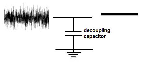
The DC signal from power supplies often have noise and look like the signal shown below.

So, basically, the signal is usually imperfect.
When coming from a power source, there are all types of interferences why AC signals come into play and superimpose on the DC signal and make the signal noisy.
What we want to do is decouple this noise (the AC signal) from the DC signal, allowing for a much cleaner DC signal.
This is especially important when the DC signal is used for circuits such as logic circuits. This is because logic chips need very precise DC voltages in order to work properly. For example, if a logic chip operates on a supply voltage of 5V, normally voltages below 2.5V will read as a LOW signal and voltages above 2.5V will read as a HIGH signal. If there is noise on the signal (AC signals on the DC signal), this can trigger in appropriate LOWs and HIGHs on the logic circuits. Thus, for circuits where precision is involved or the signal needs to simply be cleaned, decoupling capacitors are widely used.
Capacitors function very well as decoupling capacitors due to the nature of their reactance. Reactance is how a component reacts to various frequencies. Capacitors, by nature, block DC signals from passing through but allow AC signals to pass through them, since they offer less resistance to AC signals. Capacitors offer less resistance as the frequency of the AC signal increases. Thus, they are ideal for acting to decouple AC from DC signals. The AC component gets shunted to ground.
So now that we got over the conceptual aspect of decoupling capacitors, let's see how to place one in a circuit so that decoupling is achieved.
How to Place a Decoupling Capacitor in a Circuit
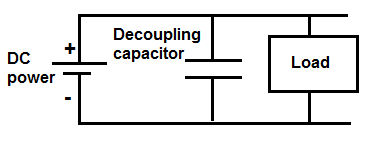
In order to place a capacitor in a circuit for decoupling, the capacitor is
connected in parallel with the power supply.

So this is a very simplified circuit, just demonstrating decoupling capacitors. You may need additional capacitors such as smoothing capacitors depending on the circuit type, but this is strictly demonstrating decoupling capacitors.
So, it's really simple, the DC power supply gives power to the circuit. The decoupling has, pretty much, infinite reactance to DC signals (resistance), so it doesn't allow DC signals to get shunted to ground. However, AC signals have much less reactance, so they can pass through the decoupling capacitor and get shunted to ground. These capacitors provide a low impedance path for high-frequency signals (which represents the noise) on the power supply, thus cleaning up the DC signal. This is how the decoupling capacitor decouples AC signals from DC signals.
Typically for decoupling capacitors, ceramic capacitors are the predominant type used. The value of the capacitor is usually between 100nF and 10nF. However, usually 100nF capacitors are used most commonly. So, the most used type of decoupling capacitor is a 100nF ceramic capacitor.
Besides power supplies, decoupling capacitors also have other uses.
One other important use of decoupling capacitors is for circuits in which there is high switching amongst components, such as logic chips for instance.
Before we spoke about logic chips needing precise voltage from a DC power supply, as to not trigger false LOWs or HIGHs. However, logic chips themselves can cause problem. If a logic chip is constantly switching logic states, for example, HIGH to LOW and LOW to HIGH, etc., it can cause transient voltage spikes in a circuit.
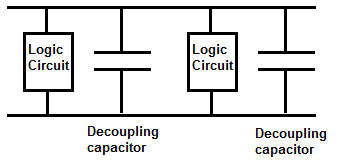
To contain these transient voltage spikes, a decoupling capacitor can be placed in parallel (very close next to the logic chip), so that these transient voltages get shunted down to ground. Today, many chips do come with built-in decoupling capacitors in the IC, but not all do. So, for those that don't, decoupling capacitors can be placed at the outputs of each of the logic gates. This prevents transient voltage spikes, which could cause unintended problems in the circuit.
This circuit with decoupling capacitors would resemble the circuit shown below.

The website, hackaday, gave an image of logic chips that used decoupling capacitors vs those that did not use
decoupling capacitors. It can be found at the following link:
Decoupling capacitors Shown in Photographs. Basically, a 74HC04 inverter was built with a decoupling capacitor and without one. The one without the
decoupling capacitor had significantly more noise on the signal.
Related Resources
What is a Bypass Capacitor?
What is a Smoothing Capacitor?
Capacitor Equations
How to Test a Capacitor
