How to Build a Diode AND Gate Circuit
In this project, we will show how to build an AND gate circuit with diodes.
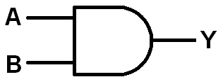
An AND gate is a logic circuit that only turns on an output when all the inputs are HIGH or a logic state of 1. If any inputs are off or at a logic state of 0, the output is off.
AND gates can be built using a variety of electronic components, including transistors and mechanical pushbuttons.
In this circuit, we will accomplish building an AND gate with simply diodes and a single resistor.
We then connect our output to this circuit which can turn on our load if all inputs are HIGH.
We will show exactly how this circuit works to achieve this logic condition.
We will build our circuit so that there are 3 inputs to the AND gate. You can change this so that there can be 2 or more. All an additional input requires is another pushbutton and another diode. You will see how to do this once you see the schematic below. We'll also explain it.
Our output will be an LED. We use a current-limiting resistor along with the LED to limit current
to the LED. However, you can modify this to suit anything else, as long as the circuit is capable of powering in on given power
requirements.
Components Needed
- 3 1N4001 diodes
- 10KΩ resistor
- 470Ω resistor
- LED
- Toggle switches (optional)
The diodes really can be any type. The 1N400X diodes are an easy type to find and very cheap, so any one from that family can be used.
The amount of diodes you need are proportional to the number of inputs you want for the AND gate. Since we are building a 3-input AND gate, we will need 3 diodes.
We use a 10KΩ as a pull-up resistor.
Optionally, you can use toggle switches to control the input values instead of having to manually connect or disconnect positive voltage or ground.
We will show how to incorporate toggle switches into this circuit so that inputs can be changed more easily.
Diode AND Gate Circuit
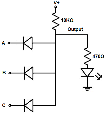
The AND gate we will build with diodes and a single resistor is shown below.
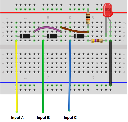
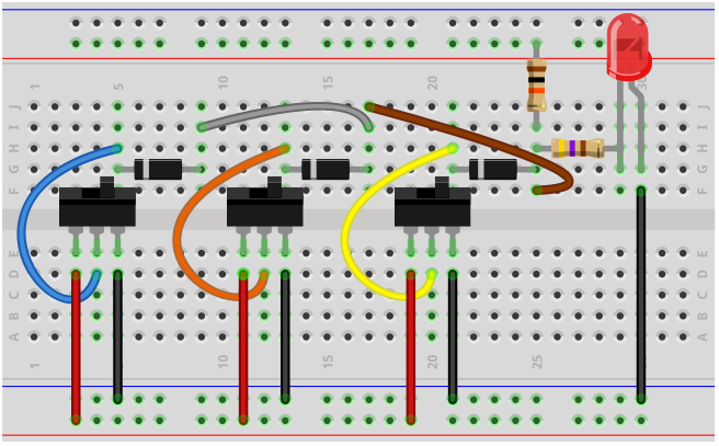
The breadboard circuit of the circuit above is shown below.
So we power the circuit with about 5V of power. This is enough to power on the LED.
The voltage we need for the circuit is considered based on the power requirements of the load. If your load needs 12V, then the voltage must be at least 12V.
So we can use 5 volts because that is enough to power on the LED.
The 10KΩ resistor is used as a pull-up resistor. It takes the voltage from the power source and concentrates it across the resistor. This voltage is then placed on each of the diodes at the anode end. So at the anode terminal of each of the diodes is the positive voltage we supply. Since we supply this circuit with 5V, there will be 5V present at the anode terminal of each of the diodes.
Now at the cathode terminal of each of the the diodes is the input. This represents the input of the gates. The cathodes are all independent of each other, while the anodes of the diodes are all tied common together.
Know that the same voltage you connected to the pull-up resistor must be connected to the inputs of the gates. It should not be a different voltage. We'll explain why below. But just know that if you're connecting +5V to the pull-up resistor, you must connect +5V to the cathodes of the diodes.
When a positive voltage is connected to the input, it connects the cathode end of the diode to +5V or a HIGH logic state.
When the input is connected to ground, it connects the cathode end of the diode to a LOW logic state.
So how the physics behind this works is like this. When an input of the gate is connected to ground, the cathode of the diode is basically at 0V, a logic LOW state. Remember that the anode terminal of the diode is connected to +5V through the pull-up resistor. So when the input is connected to ground, with the cathode at 0V and the anode at +5V, there is an electric potential difference, or voltage. When voltages are at different potentials, current can flow across. Therefore, when the input is grounded, current flows across the diode and down to ground. Voltage does not concentrate across the 10KΩ resistor.
If any of the inputs are grounded, current will always be able to flow through at least one of the diodes and down to ground. So with any input grounded, voltage will not build up across the 10KΩ resistor, which then powers the output. Instead, current leaks, so to say, and goes out to ground.
Now, if an input is connected to positive voltage, the same voltage feeding the 10KΩ resistor, a different scenario. Since the cathode is at an electric potential of +5V and the anode is also at an electric potential of +5V, there is no difference in electrical potential between the anode and cathode of the diode. With no different in electric potential, current cannot flow. Current only flows from a higher voltage to a lower voltage. If the voltages are same across the 2 terminal of a component, there is no difference to allow electrons to flow across. You could almost say it's equally pressurized. Think of voltage as a push needed to get electrons flowing. This is why a circuit cannot work without voltage. Voltage provides the force or push for electrons to flow. Voltage is normally referenced to ground. This shows how much force it gives in reference to ground, or 0V. If voltage is equal across components, there is no force, and, therefore, no current.
So in this situation, where the inputs are all to connected to +5V, no current can flow through the diodes, because they both ends are at the same electric potential. This is the reason why the voltage at the pull-up resistor and the inputs must be the same.
Since no current flows through the diodes, the pull-up resistor concentrates all the voltage from the power source and current flows through the output, which in this case is an LED, lighting it up.
So that's the physics behind it in a nutshell.
If you want to add additional inputs to the gate, you simply add more diodes in parallel to existing diodes with the cathode independent and the anode tied common with the anodes of the other diodes. If you want to remove inputs, you remove diodes.
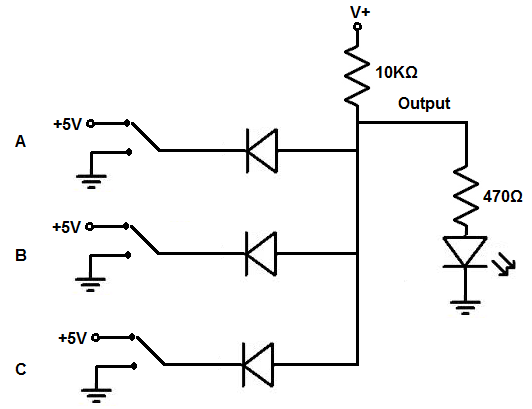
You don't have to manually connect and disconnect positive voltage or ground to the inputs. You can also simply add toggle switches instead so that it's much easier to work with.
If you want to build the above circuit with toggle switches, see Diode AND Gate Circuit built with Toggle Switches. This is the breadboard schematic of the of the toggle switch AND gate circuit, Diode AND Gate Breadboard Circuit built with Toggle Switches.
Doing this circuit with toggle switches works well because you can switch easily between positive voltage
and ground without having to connect and disconnect wires.
And this is how an AND gate circuit can be built with diodes.
Related Resources
How to Build a Diode OR Gate Circuit