
How to Build a Diode OR Gate Circuit

In this project, we will show how to build an OR gate circuit with diodes.
An OR gate is a logic circuit that turns on an output if one of the inputs is HIGH or a logic state of 1. If any 1 of the inputs are HIGH, the output will turn on. If all inputs are LOW or 0, the output will be off.
OR gates can be built using a variety of electronic components, including transistors and mechanical pushbuttons.
In this circuit, we will accomplish building an OR gate with simply diodes.
We then connect our output to this circuit which can turn on our load if at least 1 input is HIGH.
We will show exactly how this circuit works to achieve this logic condition.
We will build our circuit so that there are 3 inputs to the OR gate. You can change this so that there can be 2 or more. All an additional input requires is another pushbutton and another diode. You will see how to do this once you see the schematic below. We'll also explain it below.
Our output will be an LED. We use a current-limiting resistor along with the LED to limit current
to the LED. However, you can modify this to suit anything else, as long as the circuit is capable of powering it on given power
requirements.
Components Needed
- 3 1N4001 diodes
- 470Ω resistor
- LED
- Toggle switches (optional)
The diodes really can be any type. The 1N400X diodes are an easy type to find and very cheap, so any one from that family can be used.
The amount of diodes you need are proportional to the number of inputs you want for the OR gate. Since we are building a 3-input OR gate, we will need 3 diodes.
We use a 10KΩ as a pull-up resistor.
Optionally, you can use toggle switches to control the input values instead of having to manually connect or disconnect positive voltage or ground.
We will show how to incorporate toggle switches into this circuit so that inputs can be changed more easily.
Diode OR Gate Circuit
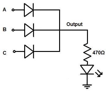
The OR gate we will build with diodes is shown below.
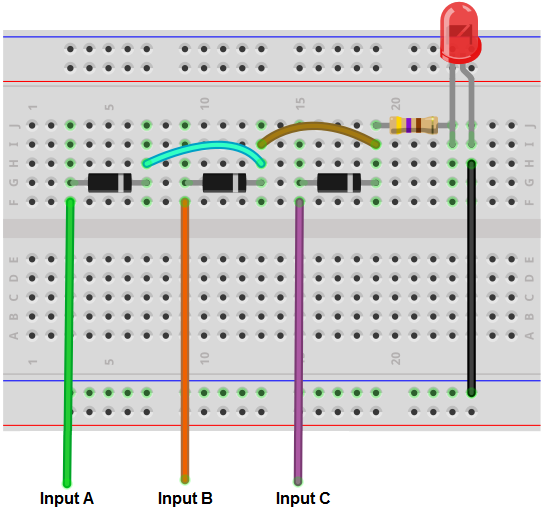
The breadboard circuit of the circuit above is shown below.
So we power the circuit with about 5V of power. This is enough to power on the LED.
The voltage we need for the circuit is considered based on the power requirements of the load. If your load needs 12V, then the voltage must be at least 12V.
So we can use 5 volts because that is enough to power on the LED.
So the inputs to this circuit connect to the anodes of the diodes. The anodes are all indepedents.
The cathodes of all the diodes are connected together, so they're common. They then connect to the output of the circuit, which is an LED along with its current-limiting resistor.
So how the physics behind this circuit works is as follows. It's very simple.
So when no positive voltage is connected to the inputs, the circuit receives no voltage. Therefore, there is no current flow to turn on and light up the LED. So with no positive voltage to any of the inputs, the output of the circuit is off.
Now, if sufficient positive voltage, +5V, is connected to any of the inputs of the gate, then this produces current flow through the diode, which then turns on the LED. Only 1 input needs +5V for the output to turn on. However, if more than 1 input is logic HIGH, the output will be HIGH as well. With an OR gate, if 1 or more inputs are HIGH, the output is HIGH. Only if all inputs are LOW is the output off.
So that's the physics behind it in a nutshell.
If you want to add more inputs, you simply add more diodes with the anode independent and the cathode connected to the cathodes of all the other diodes. If you want less, you remove diodes.
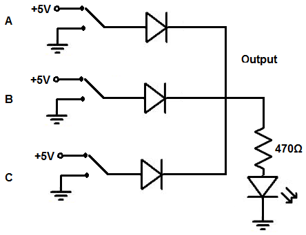
You don't have to manually connect and disconnect positive voltage or ground to the inputs. You can also simply add toggle switches instead so that it's much easier to work with.
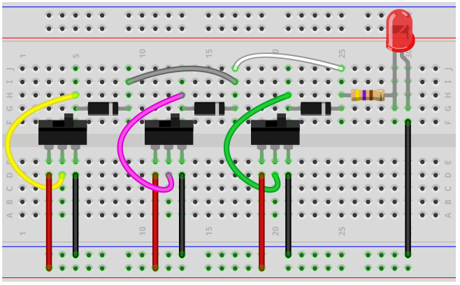
If you want to build the above circuit with toggle switches, see Diode OR Gate Circuit built with Toggle Switches. This is the breadboard circuit of the toggle switch Diode OR gate circuit, Diode OR Gate Breadboard Circuit built with Toggle Switches.
Doing this circuit with toggle switches works well because you can switch easily between positive voltage
and ground without having to connect and disconnect wires.
And this is how an OR gate circuit can be built with diodes.
Related Resources
How to Build a Diode AND Gate Circuit