
How to Build a Diode Clamper Circuit
In this project, we will go over how to build a diode clamper circuit.
A diode clamper circuit is a circuit built with a diode that shifts an entire AC signal up or down by a certain DC offset determined by the biasing values.
In other words, a diode clamper circuit clamps a signal up or down by a certain DC offset.
It doesn't change the value of the original signal. It simply moves it up or down a certain DC level. The signal itself is unchanged. Unlike a diode clipper circuit, the clamper does not cut off or restrict any part of the amplitude. It simply shifts it up or down.
A positive clamper circuit moves a signal so that all of it is above the 0V line. Thus, it's a purely positive AC voltage signal. It's always positive; it simply varies in amplitude depending on where it is during a given cycle.
A negative clamper circuit moves a signal so that all of it is below the 0V line. Thus, it's a purely negative AC voltage signal, that just varies in amplitude value depending on where it is during a given cycle.
Clamper circuits are useful anytime when DC offset is needed. Clamper circuits are used as DC voltage restorers. A pure
coupling capacitor many times will create an AC signal that straddles the 0V line and is halfway negative and positive. This is because
capacitors only allow AC signals through and block all DC signals. However, if we want to restor the AC signal back to its original DC offset,
we can simply create a clamper circuit and this puts the DC offset back in with the AC signal. This is why it's clampers are used as DC
restorers.
Components Needed for the Diode Clamper Circuit
- 1N4001 Diode
- 100nF ceramic capacitor
- 1MΩ resistor
- AC Voltage Source
- DC Voltage Source
The DC voltage source can either be batteries or a DC power supply.
Diode Clamper Circuits
We will show all all the various diode clamper circuits that can be built.
Below are 4 circuits showing diode clamper circuits clamping signals either up or down, with and without biasing.
The capacitor and the resistor forms a RC circuit that acts as a time constant, which determines the range of frequencies over which the clamper is effective.
Diode Clamper Circuit Positive Unbiased
The first circuit is a diode clamper circuit that clamps a signal above the 0V railing, making the entire signal positive.
The trough of the signal will be on the 0V line. When a positive clamper circuit is unbiased, the clamping circuit will fix the voltage
lower limit to 0V. So the trough, the peak of the bottom of the signal, will be at 0V.
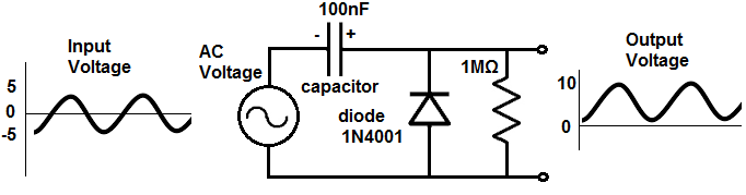
How this circuit works is as follows.
During the negative phase of the AC signal, the diode is forward biased, so current flows through the diode and the capacitor, charging up the capacitor to the 5V that the AC voltage source offers. So during this phase, the capacitor gets charged up.
During the positive phase of the AC signal, the diode is reverse biased, so no current can flow through the circuit.
So no current flows through the diode. During this phase, the voltage at the output is equal to the voltage of the AC power source and
the voltage at the capacitor. The voltage of the AC power source is 5V and the voltage at the capacitor fully charged is 5V. Adding up
these voltages gives a total voltage of 10V. So instead of going 5Vpp, the signal goes from 0 to 10V. It's the same amplitude, only clamped
up to the 0V line.
Diode Clamper Circuit Negative Unbiased
The second circuit is a diode clamper circuit that clamps a signal below the 0V railing, making the entire signal negative.
The crest of the signal will be on the 0V line. When a negative clamper circuit is unbiased, the clamping circuit will fix the voltage
upper limit to 0V. So the crest, the peak of the top of the signal, will be at 0V.
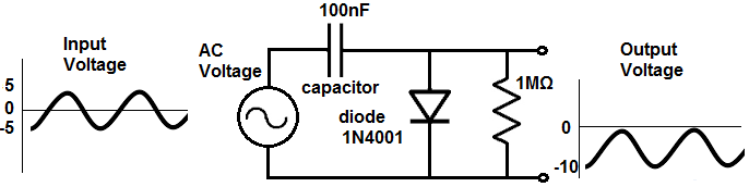
During the positive phase of the AC signal, the diode is forward biased, so current flows through the capacitor and the diode, charging up the capacitor to the 5V that the AC voltage source offers. So during this phase, the capacitor gets charged up.
During the negative phase of the AC signal, the diode is reverse biased, so no current can flow through the circuit.
So no current flows through the diode. During this phase, the voltage at the output is equal to the voltage of the AC power source and
the voltage at the capacitor. The output voltage sees the right hand side of the capacitor, which is negative and the right hand
side of the voltage source which is negative. So the voltage of the AC power source is -5V and the voltage at the capacitor fully charged is
-5V. Adding up
these voltages gives a total voltage of -10V. So instead of going 5Vpp, the signal goes from 0 to -10V. It's the same amplitude, only clamped
down below the 0V line.
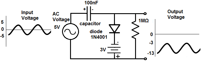
Diode Clamper Ciruit Positive Biased
Now we will build the same circuits shown above only now with DC bias, where we clamp the circuit up or down to a specific level.
We will start with clamping the positive clamper up to a specific DC level.

In order to set the clamper to a specific DC level, we must place a positive DC voltage in series with the diode.
How you determine the polarity of the DC source is to remember that the voltage output "sees" from the right side. So it "sees" from right
to left. If you are familiar with KVL (Kirchhoff's Voltage Law), you can figure out the polarity that the output sees by drawing a circular
loop from right to left, or counterclockwise. Looking at the circuit counterclockwise, you see the that the DC voltage is positive,
the capacitor is positive, and the DC voltage source is positive. since they are all positive, they all push the signal up. The DC source
is 3V. So the trough of the signal is at the 3V line. Since the signal is 10V, the peak of the signal is at 13V.
So the signal is 10V peak-to-peak, starting at 3V and ending at 13V.
Diode Clamper Circuit Negative Biased
Now we bias a diode clamper circuit so that it starts at a specific negative DC level.
In order to set the clamper to a specific DC level, we must place a negative DC voltage in series with the diode.
How you determine the polarity of the DC source is to remember that the voltage output "sees" from the right side. So it "sees" from right
to left. If you are familiar with KVL (Kirchhoff's Voltage Law), you can figure out the polarity that the output sees by drawing a circular
loop from right to left, which is the counterclockwise direction. Looking at the circuit counterclockwise, you see the that the DC voltage is negative,
the capacitor is negative, and the DC voltage source is negative. since they are all negative, they all push the signal down. The DC source
is -3V. So the trough of the signal is at the -3V line. Since the signal is 10V, the peak of the signal is at -13V.
So the signal is 10V peak-to-peak, starting at -3V and ending at -13V.
And this is the essence of diode clamper circuits. They clamp signals either up or down, with or without bias.
To see the diode clamper circuits in real life, see the following video below.
Related Resources
How to Build a Diode Clipper Circuit