
How to Build a Diode Clipper Circuit
In this project, we will go over how to build a diode clipper circuit.
A diode clipper circuit is a circuit that clips an AC voltage signal of a circuit to a certain level.
When the signal is clipped, the amplitude is reduced to a certain level, which we will bias for a particular circuit.
So, for example, an AC voltage signal feeding a circuit may be 5V; so it has a peak positive voltage of 5V and a peak negative voltage of -5V. Passing this signal through a diode clipper circuit, we can clip the positive or negative portion of the AC signal or both. So we can clip the signal to 2V for instance or clip to 1V, basically any voltage we want.
A diode clipper circuit is used for various purposes. It can be used to reduce noise in a signal. If a signal has a lot of noise associated with it, especially at the peak, then reducing the amplitude with a diode can eliminate a lot of the noise. Another purpose may just to reduce the amplitude. For example, if a very loud signal is feeding a speaker, in order not to blow out the speaker, we may reduce the amplitude with diodes.
In this project, we will show all the various clipper circuits that can be constructed, including clipped positive amplitudes, clipped negative amplitudes, and clipped positive and negative amplitudes, with and without DC bias; DC bias simply means that we clip the signal to a certain DC voltage level. Without DC bias, the signal will be clipped to the natural 0.7V of a silicon diode.
We show how to build the circuit below.
Components Needed for the Diode Clipper Circuit
- 2 1N4001 Diodes
- 1KΩ Resistor
- AC Voltage Source
- DC Voltage Source
Diodes are very easy to obtain and are cheap. The type we use is the 1N4001 but you can really use any diode from the 1N400X family.
The 1N4001 is a silicon diode. Being a silicon diode, it requires aabout 0.7V across it in order to operate. This 0.7V is a significant value, as you'll see as we discuss it below. But just know that a silicon diode needs about 0.7 volts across it in order to operate.
In this circuit, the we will use 5Vp-p, which is 5V peak to peak; this means that the positive amplitude has a peak value of
5V and the negative amplitude has a peak value of 5V.
Diode Clipper Circuits
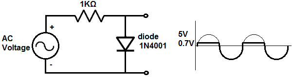
Diode Clipper Circuit with a Clipped Positive Unbiased Amplitude
The first diode clipper circuit we will build, we will clip the positive amplitude of an AC signal.
This diode circuit is shown below.
How this circuit works is as follows.
An AC signal goes through 2 phases, when it's positive and when it's negative. During the positive portion of the signal, current travels to the anode of the diode and then to ground and then repeats the process over and over again. During the positive portion of the AC signal, current flows across from the anode of the diode to the cathode. Since current flows, voltage falls across the diode and the resistor. The diode consumes about 0.7V. Silicon diodes require a steady voltage drop of about 0.7V in order to operate. Remember that voltage in parallel is the same. Therefore, since our output is in parallel to the diode, it will have a voltage of 0.7V during this positive portion of the AC signal. This is why during the positive half of the AC signal, the signal doesn't reach the peak 5V but instead has a steady DC voltage of 0.7V.
During the negative portion of the AC signal, current is impeded from travelling because current can only flow from the anode to the cathode. A diode is a one-way current device. Current can flow in from only one direction, anode to cathode. Being that no curren can flow across when the signal is negative, no voltage is dropped across the resistor or the diode. Therefore, it's as though the diode and the resistor are not present in the circuit. Therefore, at the output of the circuit is the full +5V from the AC voltage supply.
This circuit is unbiased because we are not clipping it at a certain DC voltage level, just at the voltage level that the diode uses, which is 0.7V.
Later, we will show how to bias the diode clipper circuit.
Diode Clipper Circuit with a Clipped Negative Unbiased Amplitude
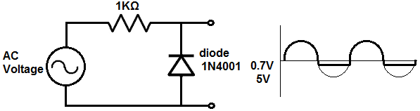
During the positive portion of the AC signal, current is impeded from flowing to the cathode, because the diode is a one-way current device. Current can only travel from the anode to the cathode, not from the cathode to the anode. Therefore, there is no current flow. Since current does not flow, there is no voltage drop across the resistor or the diode. It's as though they are not present and the output is connected directly to the AC voltage supply. Therefore, the full voltage is present at the output during the positive portion of the AC signal.
During the negative portion of the AC signal, current travels to the anode and goes across to the cathode. So current flows through the circuit. Therefore, voltage is dropped across the diode and the resistor. Being that the output is in parallel to the diode, whatever voltage is across the diode will be the voltage at the output. This is because voltage of components in parallel are always the same. A silicon diode consumes a steady 0.7V in order to operate. So during the negative portion of the signal, the signal is 0.7V straight across for the duration of the negative phase once 0.7V is reached.
This signal is also unbiased.
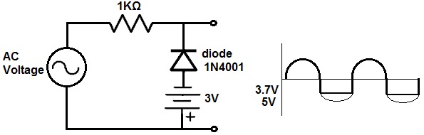
Diode Clipper Circuit with a Clipped Positive Biased Amplitude
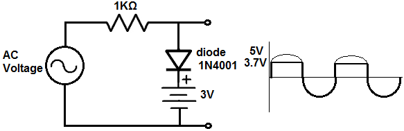
So now we will show how to bias a circuit, beginning with the positive amplitude.
To bias a circuit means to set any DC level that you want the signal clipped at. The diode always will provide 0.7V. So if we want our circuit to cut off or be clipped at 3V, then we add a +2.3 DC source in series to the diode. Both sources of voltages, the diode and the DC power supply, must be pointing in the same direction. Since the clipped portion occurs with this circuit in the positive portion of the AC signal, it is the positive amplitude that is clipped. What you have know is that the diode will always give us a voltage of 0.7V. This is because when current flows through the circuit, a diode always consumes 0.7V across it in order to operate. Now we add a DC source to bump up the 0.7V further. Since we want the circuit to clip at 3V, we must add 2.3VDC on top of the 0.7V of the diode. 2.3V + 0.7V= 3V. Therefore, this diode clipper circuits at the 3V DC level. Basically to determine any voltage level that you want all you have to do is know the DC voltage level you want the circuit to clip at, then take that number and subtract 0.7V from it, and that gives you the DC voltage source that you need to produce that clipped level.
In order for the DC level biasing to work, though, the voltage sources must be lined up so that if going from top to bottom, the
diode is + to - and the voltage source is + to -. If the voltage source were inverted in the other direction, the voltages wouldn't add but subtract. So both sources
must be + to - in order for the voltages to add.
Diode Clipper Circuit with a Clipped Negative Biased Amplitude
Now we will show how to bias a diode clipper ciruit at the negative amplitude.
Again, the diode gives us 0.7V. If we want to clip the signal at 3V, then we need to add 2.3V to the 0.7V. So we add a 2.3V DC source in series with the diode.
From bottom to top, the DC power source and the diode must both be + to - in polarity. If they are, the voltages add to give a clipped signal of 3V.
Diode Clipper Circuit with Clipped Positive and Negative Unbiased Amplitudes
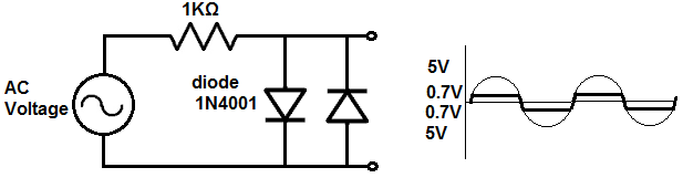
So now we show how to have clipped positive and negative amplitudes for an AC signal.
In order to have clipped positive and negative amplitudes, we must use 2 diodes. One diode is forward biased and the other diode is reverse biased. With this combination, the AC signal is clipped at both the positive and negative amplitudes.
Since this circuit is not biased to any DC level, both signals are clipped to 0.7V.
Diode Clipper Circuit with Clipped Positive and Negative Biased Amplitudes
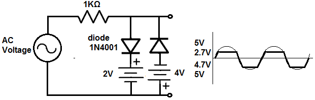
Now this circuit shows the diode clipper circuit with positive and negative amplitudes clipped with biasing.
We clip the negative signal to 4.7V and we clip the positive signal to 2.7V.
We place a 2V DC source in series with the forward biased diode. Since the diode has a voltage drop of 0.7V, the total voltage is 2.7V. Therefore, the AC voltage signal will be clipped to 2.7V during the positive portion of the signal.
We place a 4V DC source in series with the reverse biased diode. Since the diode has a voltage drop of 0.7V across it, the total
voltage is 4.7V. Therefore, the AC voltage signal will be clipped to 4.7V during the negative portion of the signal.
So these are all the combinations of clipper circuits that we can build with diodes. Truly any level can be obtained in biasing. And we showed how we can clip each amplitude, positive and negative.
Again, clipper circuits have extreme uses whenever we need to reduce amplitude for whatever reason.
To see how these diode clipper circuits work in real life, see the following video below.
Related Resources
How to Build a Diode Clamper Circuit