
How to Build an Elecret Microphone Circuit
In this project, we will go over how to build a complete microphone circuit with an electret microphone so that we can make recordings with it.
We will begin with a single electret microphone and show the connections necessary so that we can do recordings with it.
In the end, we'll make it so that the microphone circuit is hooked up to a 3.5mm jack and can plug into the microphone port of a computer. Then, we can just use any standard audio software to make a recording with our circuit.
Before we go into the specific details, we will first have an overview of what's necessary for this circuit to work.
First thing is, microphones need power. Since in the end, we will make it so that the circuit can connect into a standard microphone port on a computer, we are going to power the microphone from the power supplied from a microphone port. On most laptops and computers, microphone ports supply about 2-3 volts of power. When tested on a toshiba laptop, the voltage read from the microphone port was 2.3V. This is sufficient voltage in order to power an electret microphone. So in our circuit, we won't use an external power source such as a DC power supply or batteries but simply use the power supplied from the microphone port.
other than the power requirements, we will need a 100μF electrolytic capacitor connected in series to the output of the microphone. This is to block the DC voltage used to power the microphone from appearing on the output and creating DC offset. We only want the DC voltage used in the circuit to power on the microphone. However, the DC voltage should not appear on the output of the circuit, which is the sound signal. The sound signal is the AC signal. We want only this signal to pass through. So the capacitor aids in doing this by blocking the DC signals and passing through the AC signals to output.
Components Needed for Electret Microphone Circuit
- An Electret Microphone
- 2.2KΩ Resistor
- 100μF electrolytic capacitor
- Computer
- 3.5mm Jack
The resistor and capacitor needed can easily be obtained from most electronic online retailers.
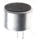
The type of electret microphone we will use is a 2.2KΩ electret microphone that requires only 2.2V of power. This is a microphone that suitable for most applications including for use with a computer. It is an omnidirectional microphone, meaning that it records from all angles of the microphone, all 360° around. This is in contrast to a unidirectional microphone, in which a user must talk into the voice side (a particular side) of the microphone for it to record at full volume.
The only other part we need is a 3.5mm plug. This can also be obtained easily through a number of online electronic retailers.
Electret Microphone Circuit
Now that we know all the components we are going to use, we will go over the circuit schematic for the electret microphone, shown below.
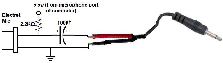
The circuit starts with the electret microphone. As stated, the microphone needs power in order to operate. This electret microphone, in particular, needs 2.2V of power in order to operate. Since the microphone port of a computer provides about 2.3V of power, this will perfectly power the electret microphone. You can connect jumper wires from the 3.5mm audio plug cable and connect the positive side to the 2.2KΩ pull-up resistor and connect the negative side to the ground terminal of the microphone. '
The other end of the 2.2KΩ resistor then connects to the anode of the microphone. This resistor serves as a pull-up resistor so that the microphone receives the voltage it needs to power on.
The only other component in the circuit is the 100μF capacitor. As stated before, this serves to block DC from appearing on the output. The DC voltage is only for biasing power to the microphone. It should not appear on the output sound signal. To block the DC and allow only the AC sound signal to pass through to output, we place a capacitor in series with the output of the microphone.
With all these connections in place, the circuit should work. If you plug the 3.5mm audio plug into the microphone port of the computer and do a sound recording, you just get very good output recording.
When I did a recording with this circuit built above, the following link is the audio recording obtained from it:
sample recording.
To see how this circuit works in real life, see the video below.
Related Resources
How to Build a Microphone Amplifier Circuit
How to Build a Touch Sensor Circuit
How to Build a Motion Detector Circuit
How to Build a Motion Detector Alarm Circuit