
How to Build a Motion Detector Circuit

In this project, we will go over how to build a simple motion detector circuit.
This is a circuit which can detect any motion or movement. It's most common use is to detect a person moving through an area where the motion detector can sense.
For example, the motion detector may be placed near a door, so that if any person passes through this doorway, the motion detector will be triggered.
The main electronic component we will use that allows us to pick up this detection is the PIR motion sensor. The PIR motion sensor is a sensor which detects movement through picking up infrared waves. Being that a person emits infrared waves, the detector is able to detect these waves and react, according to the how the circuit is designed to react. The sensor can also pick up the movement of inanimate objects as well, such a rolling ball, because as those objects move, friction acts on them, generating heat. This heat emits infrared radiation, which the PIR sensors may be able to detect if great enough.
In our basic circuit, when the motion detector circuit picks up movement, a red LED will flicker on.
Parts Needed for Motion Detector Circuit
- PIR motion sensor
- LED
- 470Ω Resistor
- 6V of DC power
The PIR motion sensor is, again, a sensor which can detect movement through picking up infrared radiation. Being that people naturally give off radiation, because of our generated body heat, the motion can easily detect people walking and moving through a vicinity within the sensor's range.
The motion sensor has a sensitivity range up to 20 feet (6 meters) and a 110° x 70° detection range, making it a wide lens detection sensor. This means it can measure 110° vertically (from top to bottom) and 70° horizontally (from left to right). The best way to check its sensitivity is when the circuit is built, try moving around through all of its angles. See at which angles it can detect your movement and at which angles it is not able to detect your movement, meaning your out of its angle scope. A lot of it is trial and error and experimenting. Once you know where it can and cannot detect, you can place it in an optimal place where it can detect in areas where you want it to.
The PIR motion sensor is a 3-pin device. Below is the pinout of this device:
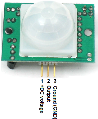
Pin 1 is the pin which receives the positive DC voltage. The PIR motion sensor needs between 5V-9VDC of power for operation. In our case, we will use about 6V of power. This can be obtained from switching a DC power supply to 6V or using 4 'AA' batteries connected in series. We will then feed this voltage into pin 1 of the PIR module.
Pin 3 is the negative DC voltage or ground pin of the device. We connect the negative terminal of the power source to this pin, for a return path.
Pin 2 is the Output pin of the PIR module. This is where the output of the PIR will leave from. When motion is detected by the PIR, its output will go high to 3V. When no motion is detected, its output low and it gives off practically no voltage. When high you can see then how it can power a load, such as an LED to light. This way we can know when it has detected motion or not.
In our circuit, we will connect a 470Ω resistor in series with an LED to the output pin of the PIR sensor. When motion is detected,
the output of the PIR sensor will swing high and power and light the LED.
Motion Detector Circuit Schematic
Below is the schematic diagram of the motion detector circuit:
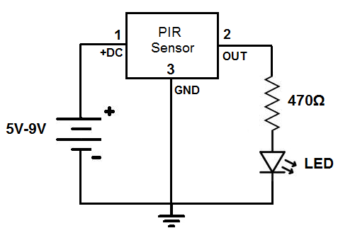
Here you can see anywhere from 5V-9V is fed into the power pins.
Connected to the output pin is an LED. We place a 470Ω resistor in series to limit current so that the LED doesn't receive excess current.
In this circuit, when motion is detected, the output voltage swings high and powers the LED. After about 1 second or 2, the output swings back low and the LED turns off until motion is detected again. Without any motion, the LED just stays off.
And this a simple motion detector circuit using a PIR module.
Check out the video below to see this circuit in action.
To build a motion detector alarm circuit, we add a SCR and a buzzer that continously buzzes when the motion
detector is triggered. To find out how to build this slightly more advanced motion detector circuit, see how to build
a motion detector alarm
circuit.
Related Resources
How to Build a Motion Sensor Light Circuit
How to Build a Hall Effect Sensor Circuit
How to Build a Vibration Detector Circuit