
How to Build a Germanium Diode Circuit
In this circuit, we will show how to build a germanium diode circuit, but more importantly how it compares with a silicon diode.
Diodes, of course, are components that allow current flow in one direction but not the other. Diodes, like transistors, are semiconductor devices that are doped in such a way that they allow flow in one way but not the other. They are used often in circuits for many reasons. Probably the most used reason they have is to protect sensitive electronic components from damaging reverse current. Since they allow current in only one direction, if placed in a circuit in reverse biased, current can't flow to damage components in a circuit that can't handle excess power.
There are 2 main types of diodes based on the material they are made from. There are silicon diodes and germanium diodes.
Silicon diodes, as the name implied, are made from silicon. They are, by far, the most common type of diode used in electronics.
Germanium diodes are made from germanium. They used to be used a lot in early electronics, such as radios, but they have largely been replaced by silicon diodes.
Even though silicon diodes are more popular today, germanium diodes still offer some advantages that silicon diodes don't.
For that reason, and in the right circuits, germanium diodes still can be used today.
We'll now go over some of the advantages and disadvantages of both diodes.
So why have silicon diodes replaced germanium diodes?
These are the advantages of silicon diodes.
Silicon diodes are much better for high current applications. If you're using a circuit that uses a good amount of current, then silicion diodes will hold up better than germanium diodes. Silicon diodes leak less reverse current than germanium diodes. If there is enough voltage to a diode in reverse biased, then the diode will leak reverse current. Germanium diodes are 1000 times more leaky than silicon diodes. Silicon diodes can also handle more reverse voltage. Depending on the diode, it can handle up to hundreds of volts. A germanium diode can handle much less. Therefore, silicon diodes are better for protection of sensitive electronic components, because they cannot handle such large reverse voltage. Another advantage of silicon diodes is that they're more stable to fluctuating temperature changes. In applications dealing with extreme temperature changes, either hot or cold, this can be undesirable if you need stability in face of temperature fluctuations. Silicon diodes are more stable and predictable in face of temperature fluctuations. However, this can be a good or bad thing, depending on the application. If you need changes based on temperature differences, germanium diodes may be the better fit.
So there are reasons why silicon diodes have largely replaced germanium diodes.
But now let's talk about the advantages of germanium diodes and why you would use them in circuits you build.
The one big advantage of germanium diodes, which could be a real game changer for a circuit, is that they have lower threshold voltages and, in combination, lower voltage drops in a circuit. The threshold voltage is the voltage required for the diode to conduct current across from its anode to its cathode. This is called forward current. Without the threshold voltage being reached, the diode cannot conduct current. Germanium diodes have a much lower threshold voltage than silicon diodes. Silicon diodes need roughly about 0.7V across it in order for current to flow. Germanium diodes need roughly 0.2V across it in order to conduct current. There is just about a half of volt less needed for current to flow. In the same way that silicon diodes need more voltage than germanium, they hold a larger voltage drop. For example, if you are feeding 3V into a circuit with a 1KΩ resistor, the silicon diode will consume 0.62V, while the germanium diode will consume 0.23V. So the silicon diode consumes 0.39V more of the voltage supply than the germanium diode. So, in lower power applications, this difference in power consumed by the diode, can be critical. This is why this is the major advantage of germanium diodes.
So if you're building a circuit where it's low power and every tenth of a volt is needed and must be allocated efficiently, you're not concerned about temperature fluctuations, the circuit doesn't use a lot of current or voltage, then germanium diodes work very well and can be used.
In this project, we will build a simple circuit consisting of a germanium diode and 1KΩ resistor. We show how a chart of the voltage consumed for a germanium vs a silicon.
Components
- Germanium diode
- 1KΩ resistor
The type of germanium diode we will use is a 1N34 germanium diode.
This diode can handle a reverse DC voltage Of 20V.
And the diode can handle a forward current of 150mA and a peak surge current of 500mA.
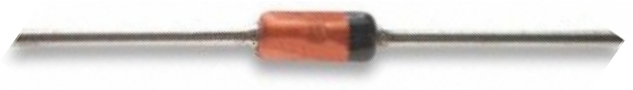
Its pinout is shown below.
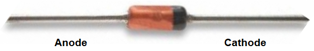
The golden colored portion of the diode is the anode. The black colored portion is the cathode. The positive voltage connects to anode and the cathode connects to ground.
We build a circuit with this germanium diode and compare the results
with a silicon diode in terms of voltage consumed.
Germanium Diode Circuit
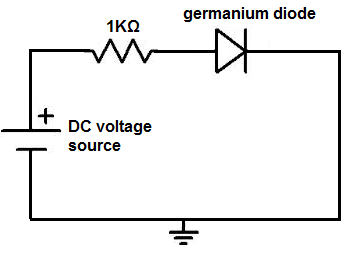
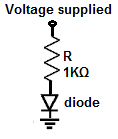
The germanium diode circuit we will build is shown below.
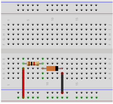
The breadboard schematic of the above circuit is shown below.
So this circuit is very basic.
It's a germanium diode in series with a 1KΩ resistor.
When connecting the circuit, the anode of the germanium diode, the golden colored part, connects to the positive voltage supply and the cathode, the black colored part, connects to ground.
The 1KΩ resistor is in series with the germanium. Components in series with a voltage supply form a voltage divider circuit. The supply voltage gets allocated between the resistor and the diode.
Depending on the amount of voltage that the supply voltage is determines the voltage allocation in the circuit.
We have supplied this circuit of a 1KΩ resistor in series with a 1n34 germanium diode with several different voltages.
Below we show a table of what voltages the germanium diode consumed (its voltage drop in the circuit) along with comparing alongside it the voltage that the silicon diode consumes for the same exact circuit (the same circuit just swapping out the germanium diode with a silicon diode).
These are the results.
| Voltage Drops Across Diode at Various Supplied Voltages | ||
 |
||
| Voltage Drop Across Diode | ||
| Voltage Supplied | Germanium Diode | Silicon Diode |
| 1V | 0.19V | 0.54V |
| 2V | 0.22V | 0.59V |
| 3V | 0.23V | 0.62V |
| 5V | 0.24V | 0.65V |
| 9V | 0.26V | 0.68V |
| 10V | 0.26V | 0.68V |
| 12V | 0.26V | 0.70V |
| 15V | 0.27V | 0.70V |
These results show you that the germanium diode consumes much less voltage than the silicon diode.
Again, if you're not using the circuit for temperature-sensitive applications, a lot of current or voltage, germanium diodes could replace silicon diodes, especially for home projects, and especially if you are using low power and need to be very efficient with power.
Then it works really well.
Related Resources
How to Vary the Brightness of an LED
How to Build an LED Driver Circuit
How to Build an LED Flasher Circuit