How Logic Gate Chips Work
Logic gate chips are truly versatile chips.
They do not have to be used just for pure logic circuits.
In fact, they have a wide range of uses.
They can be used as inverters, as active low inputs, active low outputs, active high inputs, active high outputs.
One of the most used chips is the NAND gate. This is because it is a universal gate. Any other gate that exists can be built with the right combination of NAND gates. This means NAND gates can function as AND gates, OR gateS, NOT gates, etc.
All the logic chips, though, regardless of whether it's a NAND gate, AND gate, OR gate, all function on the same basic principles.
In this circuit, it will be shown how to connect a logic chip up and how logic chips work, so that regardless of what logic
chip you are using for a circuit, you will know how to connect it and how it operates.
How to Connect a Logic Gate Chip
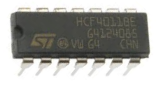
To demonstrate how a logic chip works, we are going to use the 4011 NAND gate chip as the demonstration logic chip. Remember, all logic chips are basically wired and function in the same way, so this demonstratation applies equally to other logic chips.
Below is the pinout of the 4011 NAND gate chip.
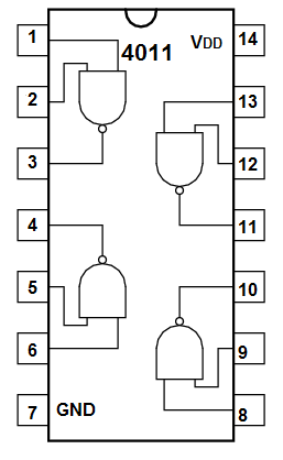
Every logic chip you get requires power. This power can be anywhere from 3V to 15V for the 4011. Check the datasheet of the logic chip you are using to find out the operating range for VDD. How much power you need depends on how much power the output load you are powering needs. For example, if you're lighting an LED, you may need only 3V. If you are powering a 12V DC motor, you will need 12V.
In a logic chip, as pretty much all chips, 2 pins are reserved for power, VDD and VSS.
To VDD, we connect the positive voltage. And VSS, we connect to GND.
These 2 pins establish power for the chip.
Apart from the power pins, all chips will have at least one gate. This chip above has 4 gates. It is a quad nand gate, meaning it is composed of 4 gates. The amount of gates in a chip will vary.
In the chip above, each gate has 2 inputs. It is a 2-input quad NAND gate. This can also vary depending on the chip in use. Some chips will have 2 inputs for each gate. Some chips may have 3 inputs for each gate. And some may have 4. Only NOT gates can have 1 input.
The thing that does not vary is each gate only has one output. In logic, period, there can only be one output for each gate.
How a Logic Gate Works
As you probably know, each gate has its own logic. AND gates, OR gates, NAND gates, NOT gates each have their own logic. The output that a logic gate will produce depends on its inputs, and this varies for each logic gate according its logic.
However, the logic chips all have in common how they decide if an input is a LOW signal and which is a HIGH signal.
How does a logic chip determine if an input is LOW (a 0) or HIGH (or 1)?
And how a logic chip makes the determination of an input as either LOW or HIGH is the same across all logic chips.
A logic chip determines an input to be HIGH or LOW based on the reference voltage of VDD/2.
Basically, we feed a voltage into VDD to give power to the chip. This voltage is important not just for power but for also biasing purposes for the circuit. When a voltage is below half of the power supply, VDD/2, the logic chip will read it as a LOW signal (as if 0V). When the voltage is above half of the power supply, the logic chip will read it a HIGH signal (as if 5V).
So in our case, if we feed 5V into VDD, any input voltage below 2.5V will be interpreted as LOW (or a logic 0). Any voltage above 2.5V will be interpreted as HIGH (or a logic 1).
And when a logic chip produces a logic 0 as its output, it outputs 0V. When it produces a logic 1 as its output, it outputs the voltage, VDD.
And this is how all logic chips pretty much work
across the board.
Related Resources
How to Build a Light Detector Circuit with a NAND Gate Chip
How to Build a Night Light Circuit with a NAND Gate Chip
How to Build a NAND Gate Logic Circuit Using a 4011 Chip