How to Build a Light Detector Circuit with a NAND Gate Chip
In this project, we will build a light detector circuit using a NAND gate chip.
A light detector circuit is a circuit that can detect light.
When a bright light shines on the circuit, such as from a flashlight, we will make it so that a buzzer turns on.
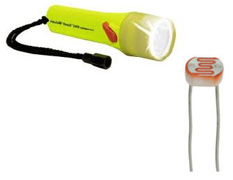
The circuit is very basic. The component that will allow us to detect light is a photoresistor. We will use a photoresistor's light-sensing ability to detect whether the circuit is exposed to darkness or bright light. How this works is that a photoresistor's resistance changes in proportion to the amount of light it is exposed to. In darkness, it has very high resistance. In bright light, its resistance drops dramatically. If placed in a voltage divider circuit with a fixed resistor, we can exploit this resistance-altering behavior so that when connected to a NAND gate, we can produce a logic HIGH output when the photoresistor is exposed to bright light and a logic LOW output when the photoresistor is exposed to darkness. All of this will be explained in detail below how exactly this works. But realize that a photoresistor's resistance-changing ability allows us to distinctly know whether it is exposed to darkness or bright light. Knowing this, we can effectively build a light detector circuit.
When exposed to bright light, we can make the circuit do anything. For this circuit, we will turn on a buzzer
Components Needed
- 4011 Quad NAND Gate Chip
- GL5537 Photoresistor
- 6.8KΩ Resistor
- 3V buzzer
The 4011 chip can be obtained very cheaply from a number of online retailers for just a few cents. One place it can be obtained from is Tayda Electronics at the following link: Tayda Electronics- 4011 Quad 2-Input NAND Gate IC. However, it is a very popular chip and many electronics parts suppliers have them.
The 4011 is a quad NAND gate chip. It is a chip that is made up of 4 independent NAND gates.
The pinout of the 4011 quad NAND gate chip is shown below, so that you can see how to connect it in the circuit.
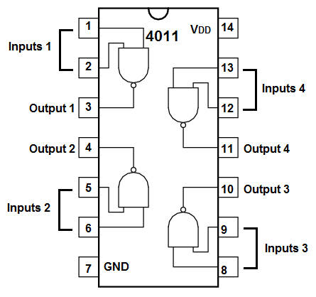
Each NAND gate has input pins and 1 output pin.
The following chart shows NAND gate logic, which shows what output a NAND gate chip will produce for a set of given inputs.
| NAND Gate Logic | ||
| Inputs | Output | |
| 0 | 0 | 1 |
| 0 | 1 | 1 |
| 1 | 0 | 1 |
| 1 | 1 | 0 |
This means that if one of the inputs are a 0, the NAND gate will output a logic HIGH at its output, which means the output will be drawn up to VCC and the load will be powered. If both inputs feeding into the NAND gate are a 1, only then will the NAND gate output a logic LOW at its output, which means the output will be drawn down to GND, and the load will not be powered.
In our circuit, we will use both of these cases.
The other component we need is an LED along with a 330Ω current-limiting resistor to protect the LED from excess current.
The 6.8KΩ resistor that we will use in this circuit to form a voltage divider may have to be adjusted depending on your photoresistor. Test it out. When you shine bright line on
the photoresistor, make sure its resistance is below 6.8KΩ. If not, choose a resistor that is greater than the resistance that the photoresistor has when bright light is flashed on it. 6.8KΩ may
be too low if your photoresistor does not reach a resistance this low. But if it is a GL5537, then it should go way below 6.8KΩ and you won't have to do any adjustment.
Light Detector Circuit Using a NAND Gate
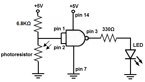
The schematic diagram of the light detector using a 4011 NAND gate chip is shown below.
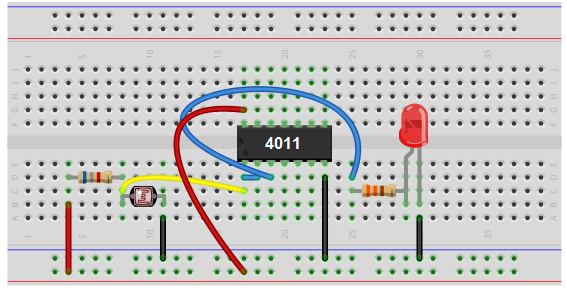
Below is the breadboard schematic version of the above circuit so that you can see the exact wiring of the circuit to the 4011 chip.
First and foremost, we must give power to the 4011 NAND gate chip. We will feed it 5V of power, so we give +5V to pin 14 and we connect pin 7 to GND. This establishes power to the chip.
The circuit is very basic. The component that allows us to detect light is a photoresistor. We set up a voltage divider circuit composed of a photoresistor and a 6.8KΩ fixed resistor. In a voltage divider circuit, voltage is distributed across the components in direct proportion to the amount of resistance each component offers. The more resistance a component offers in relation to the other, the more voltage that will fall across that component. This is shown in the ohm's law formula, V= IR. You can see the direct relationship between voltage and resistance in the formula. The greater the resistance a component offers, the more voltage that falls across it. Conversely, the less resistance a component offers, the less voltage that falls across it.
When a photoresistor is exposed to darkness, it has very high resistance, in the order of a few megohms (MΩ). With resistance this high, most of the voltage from the power supply feeding the voltage divider circuit falls across the photoresistor, with very little voltage falling across the 6.8KKΩ fixed resistor. Thus, when connected to the inputs of NAND gate, with voltage so high, the NAND gate will essentially interpret the voltage divider as if it were HIGH (or 1). When the voltage feeding the inputs of a NAND gate are greater than half of the power supply voltage, it will interpret it as a HIGH value. Since we will tie both inputs together, the NAND gate will interpret this as two ones, so it will output a 0 (or LOW), which means the output will be drawn down to GND and the load will not be powered.
Remember, NAND gate logic, two 1s gives a 0. This is the only time we get an output value of 0 in NAND gate logic. If a 0 is present anywhere in the inputs, including twice, the NAND gate will output a 1.
When a photoresistor is exposed to bright light, its resistance drops dramatically, in order of 20-30KΩ, or less, depending on the type in use. With this resistance this low, most of the voltage from the power supply falls across the 33KΩ resistor, and less than half falling across the photoresistor. With voltage this low, the NAND gate will interpret as a logic level of 0. Thus, the output will be drawn up to VCC and the load, the buzzer, will be powered on.
So you can see how this voltage divider circuit allows us to get 2 different logic levels produced by the
NAND gate chip in different lighting conditions.
Related Resources
How to Build an Arduino Light Detector Circuit
How to Build a Night Light Circuit with a NAND Gate Chip
How to Build a NAND Gate Logic Circuit Using a 4011 Chip
How to Build a Touch Sensor Circuit with a NAND Gate Chip