How to Build a DC Motor Circuit
In this project, we will go over how to connect a DC motor to a circuit so that we can build a DC motor circuit which can either rotate forward, reverse, or bidirectionally.
This is valuable because DC motors can tremendous applications and are used in all types of electronics products, such as vehicles (wheels to spin), fans (spinning blades), power drills (spinning of the drill either forward or in reverse) and much, much more. The world world not be the same today if it wasn't for motors.
Before we go into how to build the circuit, however, we will go over what a DC motor is, so you can have proper background and education on this topic.
A DC motor is a motor which runs off of DC power.
This means that a DC motor works off of direct current (DC), not alternating current (AC). This means that DC motors work off of AC power rectified or batteries.
Now that you know the type of power off of which DC motors operate, let's go into the internal construction of a DC motor, which helps to understand how it operates in a circuit.
A DC motor is made up of a stator, which is a permanent magnet, with an electromagnet made to circulate,
or rotate, around this permanent magnet.
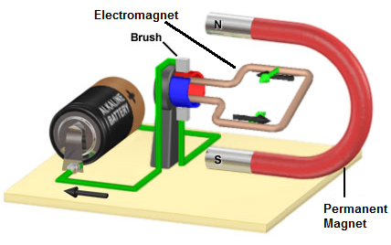
The magnet is called a stator because it is fixed; it doesn't move. The electromagnet, the turning coil of wire, is called an armature, or rotor, because it rotates about the permanent magnet.
The electromagnet carries current produced by the battery; a wire which current flowing through it
generates a magnetic field. This magnetic field attracts it to the permanent magnet and what allows it to spin about the
permanent magnetic. The interplay of the magnetic field from the permanent magnet and the moving charged electrons in the current
creates torque, which is the spinning motion of a DC motor.
DC Motor Circuit
To connect a DC motor to a circuit simply so that it will spin is very easy.
All you have to do is connect the amount of DC voltage to the motor which it is rated for. Therefore, for a DC motor rated at 9 volts, all you must do is connect 9V to the circuit.
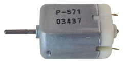
Below is a Nichibo PC-280P DC motor, which operates on 3-18VDC. This means it can operate on any voltage
between 3-18 volts of power. In the circuit below, we give it 9VDC.
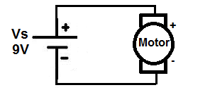
When DC voltage is supplied to a DC motor, positive lead to positive lead and negative to negative, the DC motor spins in a forward direction.
DC Motor Circuit in Reverse
Now if we reverse the voltage going to the DC motor, so that the battery or DC voltage is flipped around, so that positive voltage is now going to the negative lead of the motor and the ground of the DC voltage or battery is going to the positive lead of the motor, the motor will spin in the opposite direction, or in reverse.
Below is the circuit schematic of the DC motor now in reverse:
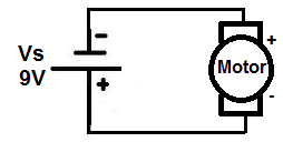
Now the motor will spin in the opposite direction with the polarity switch.
A Bidirectional DC Motor Circuit
Now how can we build a DC motor circuit which is capable of spinning forward and in reverse with the flip of a switch, so that the motor can spin forwards or backwards when we want it to. This has tremendous applications in many different items. Think of a car that goes forward when in one gear and goes in reverse in another. The motor of the car spins forward for forward drive and then in the reverse direction to go in reverse. Also think of a power drill which goes forward to drill a nail in the wall and then in reverse to take a nail out of the wall.
To build a bidirectional DC motor circuit, we need to use a switch, so that we can go back and forth when we want between forward motion and reverse motion. And the type of switch which is best for this is a Double Double Throw (DPDT) switch. This will allow us to make connections to the DC motor so that in one direction, the positive voltage is connected to the positive lead of the DC motor and the ground of voltage is connected to the negative lead of the DC motor, and in the other way, the positive voltage is connected to the negative lead of the DC motor and the ground voltage is connected to the positive lead of the motor. This will allow forward and reverse voltage with the flip of a switch.
Below is the bidirectional DC motor circuit which allows forward and reverse motion with the flip of
a switch:
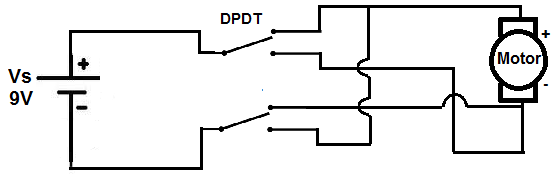
When the switch is up, the motor spins in the forward direction. When the switch is thrown down, the motor spins in the opposite direction. Again, this is how cars, power drills, and many other equipment work.
How to Control Speed of a DC Motor
The last thing that can be varied, besides direction, in a DC motor circuit is speed. And to vary speed
is also a simple concept. To decrease speed, the voltage supplied to the motor needs to be decreased. And to increase
speed, the voltage supplied to the motor needs to be increased. So if a motor can operate on 3-18V, 3V is when it will
operate at its slowest speed. 9V will be its median speed. And at 18V is when it will go the fastest it can go. The
quantity of voltage varies speed in a motor.
Related Resources
DC Motor Specifications- Explained
How to Build an H-bridge Circuit
How to Build a Servo Motor Circuit