
How to Build a Servo Motor Circuit (with Arduino)
In this project, we will go over how to build a servo motor circuit using an arduino.
This is a circuit which can control and rotate a servo motor to rotate a certain amount of degrees.
Specifically, in our circuit, we will make it so that the servo motor rotates 180 degrees and then stops and then rotates 180 degrees back (in the direction it began).
To control the servo, we connect it to the arduino board and then program it so that rotates in the manner discussed
before. We'll see how we do this in code.
Background on Servos
Servos are motors that are used to accurately control physical movement. This is because they generally move to a position instead of continuously rotating. They are ideal for making something rotate over a range of 0 to 180 degrees.
Servos are easy to connect to the arduino and control, because the motor driver is built into the servo. This means that the driver circuit to operate the motor is internally constructed into the servo. So we don't have to connect a driver circuit, since it already is connected. Thus, all we do is connect the pins of the servo directly to the arduino board and program it, and that's all that needs to be done.
Internally, servo motors contain a small motor connected through gears to an output shaft. The output shaft drives a servo arm and is also connected to a potentiometer to provide position feedback to an internal control circuit.
Continuous rotation servos that have positional feedback disconnected can rotate continuously clockwise and counterclockwise
with some control over the speed. These function like brushed motors, except that continuous rotation servos use the servo library code
instead of analogWrite and don't require a motor shield. The disadvantages are that the speed and power choices are limited
compared to external motors, and the precision of speed control is usually not as good as with a motor shield (since the electronics
is designed for accurate positioning, not linear speed control).
Components Needed
- Servo Motor
- Arduino
- 3 pin male to male header
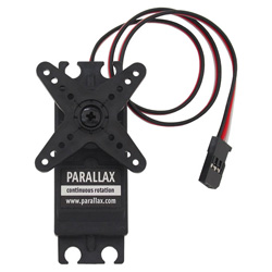
The servo motor from Parallax is a good standard motor that can be used for this project. It is a motor that can hold any position between 0 and 180 degrees. And it works between a operating voltage of 4V to 6VDc. Thus, it can function well with the power pin connected to the 5V terminal of the arduino.
The motor can be found at the Parallax site at the following link: Parallax- Standard Servo Motor.
The datasheet for the motor can be found at the following link: Parallax Servo Motor Datasheet.
The motor has 3 terminals, the power pin, ground, and output.
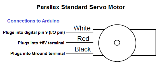
The different pin terminals are differentiated on the servo motor by their colors. The red wire is the positive voltage pin.
This is the pin that gets fed the 5V from the arduino pin so that the power can be powered and run. The black wire is ground. This gets
connected to the ground terminal of the arduino board. The white wire is the I/O wire. It gets connected to digital output pin D9 of
the arduino.
Parallax
Wire
Connects to Arduino Terminal
Red
Wire
+5V
terminal
Black
Wire
GND
terminal
White
Wire
D9
(digital output pin)
Servo Motor Circuit Schematic
The circuit shcematic we will build is shown below.

So you can see all connections of the servo made to the arduino board.
All we need now is the code to make the servo rotate.
Code
The code is shown below.
#include <Servo.h>
Servo myservo;
int angle=0;
void setup()
{
myservo.attach(9);
}
void loop()
{
for (angle=0; angle<180; angle+=1)
{
myservo.write(angle);
delay(20);
}
for (angle=180; angle>=1; angle-=1)
{
myservo.write(angle);
delay(20);
}
}
So this is the basic code to make the servo rotate 180 degrees and then rotate back 180 degrees. To work, as shown in the code, you must include the Servo.h library code.
To see how this circuit works in action, see the video below.
To see a modified version of this circuit, with the arduino spinning faster, watch the video below.
To create this, in the code, change 180 in both for loops to 360. And change +1 and -1 in the for loops to +10 and -10, respectively.
Related Resources
How to Build an H-bridge Circuit
How to Build a Dark-activated Light Circuit
How to Build a Hall Effect Sensor Circuit
How to Build a Touch Sensor Circuit
How to Build an Accelerometer Circuit
How to Build a Motion Detector Circuit
How to Build a Motion Detector Alarm Circuit