
How to Connect a PNP Transistor in a Circuit
This article will show how to connect a PNP Transistor in a circuit for switching or for amplification.
A PNP transistor is just like an NPN in terms of function, what it accomplishes in a circuit. Like any transistor, a PNP provides amplification and/or switching capabilities to turn a load on or off connected to it. This is exactly like an NPN.
The difference in the PNP transistor from the NPN is how power is biased to the transistor for it to function.
Let's review the more commonly used NPN transistor. An NPN transistor receives positive current to the base. The more current it receives to the base (within limit), the more the transistor conducts across from collector to emitter. If there is no base current, the transistor is off. There must be sufficient base current for an NPN transistor to turn on. And the more the base current is increased, the more this base current is amplified, so the more current flows across from collector to emitter.
A PNP transistor works differently. A PNP transistor is fully functional when there is no current flowing to the base. Instead current is sinked from the base of the PNP transistor, meaning current flows out of the base and is sinked to ground. There is negative current flow to the base. In this condition, the PNP transistor will conduct current across from the emitter to the collector, as long as the voltage that the emitter is receiving is more positive than the base. When the base current is increased, the less current there is that flows from the emitter to collector, until the current is increased to the point where current flow ceases from emitter to collector.
So with an NPN transistor, the more base current there is, the more this increases the flow of the amplified current. With a PNP transistor, the more base current there is, the more the flow of current is impeded until all current completely stops if the base current reaches a high enough level. This is the main difference between NPN and PNP transistors.
So now that we've gone over the basics of PNP transistors, we can now go over how to connect a PNP transistor in a circuit to provide switching and/or
amplification.
PNP Transistor Pinout
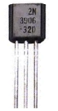
The PNP transistor, like almost all transistors, is a 3-lead device. We will use the most widely used PNP transistor for our circuit, the 2N3906.
Going from a back view, the first lead is the emitter, the second lead is the base, and the third lead is the
collector.
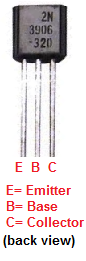
The base lead is the lead which controls the flow of current from emitter to collector. In a PNP transistor, with sufficient negative base current and sufficient positive voltage at the emitter, current will flow across from emitter to collector and power any device connected.
The emitter is the source of current flow of a PNP transistor, meaning this is where the current flow is initiated. To get current flow, positive voltage must be hooked up to the emitter terminal that is greater than the voltage input at the base lead. The holes in the P material will be repelled by this positive charge and flow downward toward the collector.
The collector is where current flows to from the emitter. Usually, the load device which we want to power is connected to the collector side of the transistor. This is because the collector is the largest, most heavily doped area of a transistor that connects the greatest amount of charge. Amplified current is slightly greater at the collector side than the emitter side. This is why most loads to be powered are connected to the collector region.
And this is really the basic way in which PNP transistor circuits are formed. The main thing to remember is that current at the base lead impedes flow, not increases it. So this is why we connect it to ground. This establishes a negative current flow to ground at the base terminal.
So now we will build our actual circuit.
Components Needed
- 2N3906 Transistor
- 330Ω Resistor
- LED
- 5 'AA' batteries or Dual DC Power Supply
- Normally Open Switch
So these are the components we need to build and demonstrate a PNP circuit.
PNP Circuit
Below is the circuit for connecting a PNP transistor, which can function as a switch or an amplifier.

So +3V is connected to the emitter of the transistor. And a normally open pushbutton is connected to the base of the transistor. Unless it is pressed, normally no current flows into the base of the transistor. Thus, it is fully on when not pressed. Therefore, the LED connected to the collector of the PNP transistor will be on. However, if the push button is pressed, the transistor will turn off and the LED will shut off. This is because the base voltage will be greater than the emitter voltage, which blocks current flow.
And this is how a basic PNP transistor circuit works.
To see how this circuit works in real life, see the following video below.
Related Resources
How to Connect a Transistor as a Switch in a Circuit
How to Connect a (NPN) Transistor in a Circuit
Types of Transistors
Bipolar Junction Transistors (BJTs)
Junction Field Effect Transistors (JFETs)
Metal Oxide Semiconductor Field Effect Transistors (MOSFETs)
Unijunction Transistors (UJTs)
What is Transistor Biasing?
How to Test a Transistor