
How to Connect a Transistor as a Switch in a Circuit

In this article, we go over how to connect a transistor so that it will function as a switch in a circuit.
A transistor is a component that can play 2 vital roles. It can function as a switch and an amplifier. Many times, it functions as both in a circuit.
Specifically, in this article, we will show how transistors can be used as switches.
Why Transistors Are Used as Switches
Before we go into how to wire it up, let's go over first why transistors are used in circuits as switches.
Think about it for a moment. There are tons of different switches.
There are pushbutton switches, rocker switches, slide switches, dip switches, key switches, toggle switches, knife switches, that play the same function as a transistor. It switches a load on or off that is connected to the output side of the switch
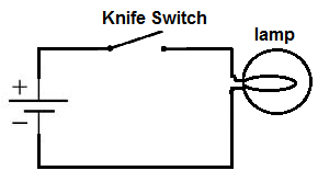
The below circuit uses a knife switch to turn the load, the lamp, on or off.
So why are transistors used so frequently as switches in circuits if these switches above have the same use?
And the reason is that transistors are electrical switches. Unlike all the switches above, which are mechanical switches, a transistor turns on or off by electrical current. Mechanical switches, such as knife switches, pushbutton switches, need human intervention- someone to press them down and pull them back up. Transistors, however, turn on and off, not by physical human intervention, but by electrical current.
Both have their own uses. Mechanical switches are used mostly outside of electronic circuitry where it is desired that humans control various functions such as an ON-OFF switch for turning on or off a device, volume control, etc.
Transistors are used when we want to switch devices on or off when only current can the on-off state of the transistor.
As a prime example of where transistors function perfectly as electrical switches, we will go through a few example circuits below.
How to Connect a Transistor as a Switch in a Circuit
So now that we know the theory of why transistors are used as switches, let's go over how to connect a transistor to function as a switch in a circuit.
A transistor is a 3-pin device composed of a base, collector, and emitter for bipolar junction transistors (BJTs).
Below is the pinout of a BJT:
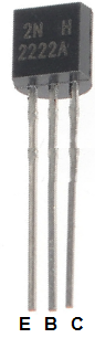
Looking at the back side of the transistor, the emitter is the first pin, the base is the middle, and the collector is the third.
To connect the transistor as a switch in a circuit, we connect the output of the device that will switch on the transistor to the base of the transistor. The emitter will connect to ground of the circuit. And the collector will connect to the load that the transistor will turn on and the supply voltage of the circuit.
The setup to set the transistor up as a switch is shown in the diagram below:

The output of the device that outputs a current will be connected to the base of the transistor. The load will be connected to the collector as well as the positive DC voltage for NPNs. The emitter will connect to ground.
Below is an example of a transistor functioning as a switch in a circuit:
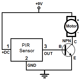
There are a few different parts in this circuit. But the part which detects the motion is the PIR motion sensor. When motion is detected by this sensor, it converts this motion into an electrical current. Many electronic devices do this. They convert mechanical into electrical current. The PIR motion sensor does this. Once it detects motion, it outputs current to its outpin pin, which is pin 3. Since this output is current, it can be used to turn on the transistor.
Since the PIR motion sensor outputs current and the transistor is a switch that turns on by electrical current, it's a perfect switch that works complementary with the transistor. A mechanical switch is when a human needs to press down to operate it. A transistor is when an electrical current switches something on. So, again, transistors are used when we want electrical current to control the state of switches in a circuit.
When the PIR sensor detects no motion, it outputs no current, so the transistor does not turn on. When the transistor does not receive sufficient current at its base, no current can flow from emitter to collector to power the load, which in this case is a motor.
Even though the collector of the transistor needs positive voltage (for an NPN transistor) in order to operate, it will not turn on just because voltage is attached to it. This is because the transistor acts as an open circuit when it does not receive sufficient base voltage. When a transistor acts an open circuit, no current can flow down to ground. So the +9V of DC voltage that is supplied to the DC motor has no electric potential. It is +9V positive across both terminals of the motor, so, again, there is no electric potential. Only when the transistor turns on and current can flow down to ground is there an established electric potential. This is now when current can flow. Current can only flow when there is an electrical gradient of voltage.
When the motion detector detects motion, it outputs a current from its output pin to the base of the transistor. This electrical current switches the transistor on, so the transistor can now power its load, which is the motor.
In this circuit, the transistor acts as a switch and an amplifier. The same setup to set the transistor as a switch is also to set it up as an amplifier.
If using a PNP transistor, negative voltage is supplied to the collector.
Related Resources
How to Build a Temperature Sensor Circuit
How to Build a Hall Effect Sensor Circuit
How to Build a Motion Detector Circuit
How to Build a Vibration Detector Circuit