
How to Connect an Adjustable Voltage Regulator
In this article, we'll explain how to connect an adjustable voltage regulator to output the desired voltage that you want it to pass out.
An adjustable voltage regulator is a regulator that can be adjusted to output any voltage from the range that the voltage regulator is designed to output.
A LM317T voltage regulator, which is what we are going to use in this setup, can be adjusted to output from +1.2V to 37V.
And how do we modify the voltage to that which we want output?
We do this by changing the value of the resistor connected to the Adj pin of the voltage regulator.
A voltage regulator has 3 pins:
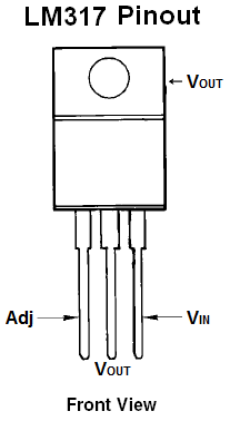
Look from the front, the first pin (on the left) is the Adjustable Pin, the middle is Vout, and the last pin(on the right) is Vin.
Now that you know the pins, let's see how the circuit is set up:

Here you see we connect two resistors to the voltage regulator. These resistors determine the voltage that the voltage regulator adjusts to and outputs.
The voltage that the adjustable regulator outputs is determined by the equation below:
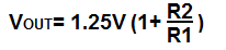
Therefore, you can see based on this formula, that the more the value of resistor R2 increases, the greater the voltage output.
In our setup now, these are the values we're going to use. We're going to put 12 volts into the voltage regulator and regulate it down to 5V. Based on the formula above, in order for the LM317 to output 5 volts, the value of R2 must be 720Ω. Set this above circuit up and then use a multimeter to check the output voltage by placing it across the 1µF capacitor or across the the resistors. You will discover it's very close to 5 volts. Now swap out the R2 resistor and place a 1.5KΩ resistor in its place. Now the voltage output should be near 10V.
This is the advantage of adjustable voltage regulators. You can adjust it to any voltage within the range that the voltage regulator supports.
Note: The capacitors C1 and C2 are used to clean up the power line. C1 is optional and it's used to clean up transient response.
C2 is needed if the device is far from any filter capacitors. This capacitors helps smooth out the power supply line in case of abrupt current spikes.
Related Resources
LM317 Voltage Regulator
How to Test a Voltage Regulator
How to Build a Zener Diode Voltage Regulator