
How to Create a Delay using the SysTick Timer with an STM32 Microcontroller Board in C
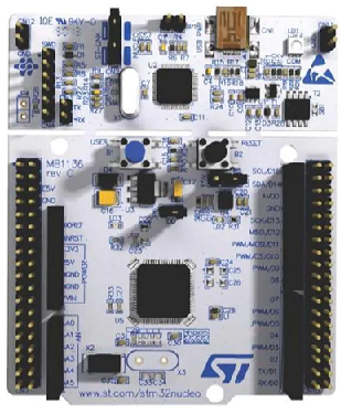
In this article, we explain how to create a delay using the SysTick timer in an STM32 microcontroller board in C.
The SysTick timer is unique timer and differs from general timers found on an STM32 microcontroller board, because it is found in the processor of the chip on board. General timers are peripheral devices that are part of the microcontroller and are placed there by the microcontroller manufacturer. The SysTick timer is found on the processor and placed there by the chip manufacturer (not the board manufacturer) and is found in all ARM Cortex microcontrollers, regardless of the board manufacturer.
The SysTick timer is used for taking actions periodically. According to the processor manufacturer ARM, it is often used as a time-base for real-time operating systems or just as a simple counter.
The SysTick timer is a 24-bit down counter driven by the processor clock. It counts down from an initial value down to zero. 24 bits implies a maximum initial value of 224= 16,777,216. This means that in hexadecimal, the initial value can be set to a value between 0x000000 to 0xFFFFFF.
So, again, the SysTick timer, also referred to as the System Timer, is derived from the processor.
Therefore, if you want more information about it, you refer to the datasheet from the processor manufacturer, not the microcontroller manufacturer. You wouldn't refer to the STM32 datasheet for the SysTick timer, but the Cortex-M4 processor datasheet, which is shown at the following link: Cortex-M4 Devices- Generic User Guide.
Taking the information from the datasheet, the associated registers for the SysTick timer are shown below.
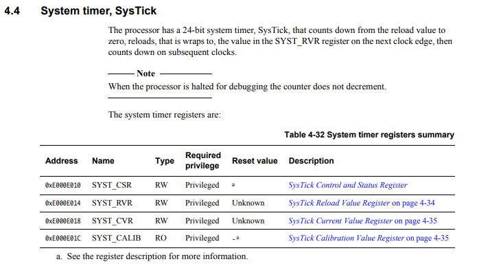
So these are the registers we will have to configure in order to get our desired delay using the SysTick timer.
For this project, we want to get a delay of 1 second.
So let's go over how we achieve a delay of a certain time with the SysTick timer.
So in order to get a delay of a specific time, we have to feed a value into the SysTick Reload Value Register.
This value is calculated by the formula, Reload Value= (System clock)(Delay Desired)
The delay desired is the time you want the delay to last in unit second.
The SysTick timer is always derived from the System clock. Usually this value for STM32 boards is 16MHz. You can find this value in the datasheet for the STM32 board you are working with.
Thus, if we want a 1-second delay, our formula would look like the following, Reload Value= (16,000,000)(1 second)= 16000000
Therefore, if you want a delay of 1 second, we have to load the value, 16000000, into the SysTick reload value register.
You can modify this value and see the results for yourself.
This website has a SysTick Reload Value Register Calculator.
The calculator takes in the system clock (SYSCLK) and the delay desired as inputs, and, as output, gives the SysTick reload value.
So knowing this, let's now go into the code that creates a 1-second delay from the SysTick timer.
We will put the 1-second delay into an infinite loop that toggles an LED. With the delay in place, the LED will be toggled on and off every 1 second.
We need 3 major code files in order for this code to work.
We need our header files, which contains many macros and structures that describe the various registers and needed values. We create a separate header file for the SysTick register map.
We then need our main C file, which contains the code that creates our 1-second delay created by the SysTick timer.
In this project, we will toggle the onboard LED at GPIO PA5, so that it toggles on and off each second. This 1-second delay is created by the SysTick timer.
Below are the 2 header files that we will need for our code, which in this case is named, stm32f446.h and systick.h
If you want to, you can combine both, you can do that as well.
The header file containing the macros and structures for the SysTick timer is shown below.
The contents of the main.c file is shown below.
The first thing we must do is include the stdint.h header file and our stm32f446xx.h and systick.h header files in our main.c file.
Next we have the function prototype for the sysTickDelay() function so that the compiler knows what the function returns and what input(s) it takes in, along with their types.
After this, we have our main() function.
Because we are going to turn on an LED on and off at GPIO PA5, we need to turn on the peripheral clock for GPIO Port A and set pin PA5 as an output pin.
We then have our infinite loop.
We toggle the LED through the line, pGPIOA->ODR ^= (1 << 5);
We then use the sysTickDelay() function to toggle the LED each 1 second.
Now let's take an in-depth look at this sysTickDelay() function so that you can understand exactly how it works.
So the function takes in a single parameter, an integer named, delay.
If you need a decimal value, then you would have to change the variable from type int.
So the first thing, we do is set the SysTick Reload Value Register to the value we need to create a 1-second delay.
Because we want a 1-second delay, the value we give to the SysTick Reload Value Register is 16000000.
This SysTick Reload Value Register is shown below.
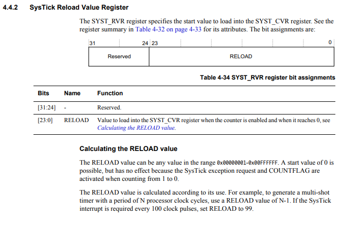
Keep in mind that the maximum value you can feed into the reload register is 0xFFFFFF, which is 16777215. With a 16MHz internal clock, this would produce a delay of approximately 1.048 seconds. You cannot create a delay longer than this. However, because the function has a for loop in it, you can loop multiply the delay any amount of times you want.
We want to clear any value that may be in the current value register so that we start from scratch.
This SysTick Current Value Register is shown below.
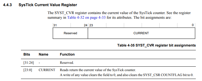
This register holds the current value of the countdown and it does not need to manually manipulated in any way during the countdown process.
It only needs to be manipulated if you are clearing it out.
Next, we modify bits in the SysTick control and status register.
This is shown in the diagram below.
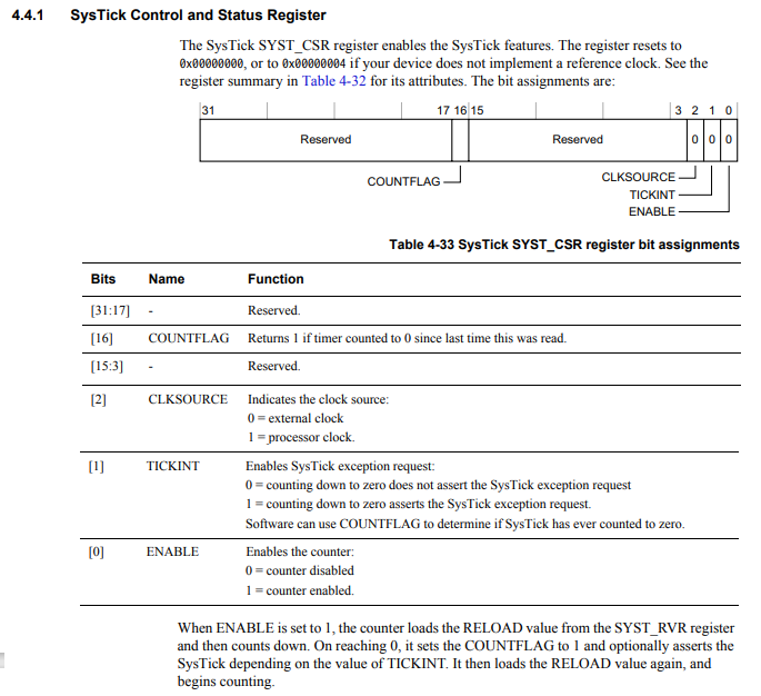
With this register, we both enable the SysTick counter and we select the processor clock as the system clock for the SysTick timer. The processor clock would be the internal RC clock which has a frequency of 16MHz.
Setting bit 0 to 1 enables the SysTick counter.
Setting bit 2 to 1 selects the processor clock as the system clock.
We then have our for loop, which allows us to multiply our delay time as many times as we want. For example, we create a 1-second delay with the reload value we entered in. However, if we need a 10-second delay, we don't modify the reload value because it's almost already at its maximum with a 1-second delay. Instead, when we call the sysTickDelay() function, we pass in 10 as its parameter. This way, the code goes through 10 loops of 1-second delays, creating a delay of 10 seconds.
Within our for loop, we have the statement, while(!(pSysTick->CSR & (1 << 16)));
This line waits until the countflag, bit 16, returns a 1, which means that the counter has counted down all the way from its initial value to 0. This means that the time period for the timer has elapsed and complete its entire cycle. When this is met, we exit the while loop.
We then disable the SysTick counter in the control register, and then the process starts all over again.
So this is how we can create a delay using the SysTick timer using an STM32 board in C.
Related Resources