
How to Create a Timer Interrupt Driver with an STM32F446 Microcontroller Board in C
In this article, we explain how to create a timer interrupt driver with an STM32F446 microcontroller board in C.
With a timer interrupt driver, we can have a timer running in the background that can execute some specific task at some specific interval we determine.
In our program, we will have a timer interrupt driver which will have a 1-second delay and toggle an LED every second.
Previously, we created a program on, How to Create a Delay using a General-purpose Timer with an STM32F446 Board in C. If you need to, please familiarize yourself with how to create a delay with a general-purpose timer first before using interrupts, because we will not go over that code as extensively; we will simply be going over how to turn that code into it being done with an interrupt driver.
So we take this program and modify it a bit by enabling the UIE interrupt bit in the TIMx DMA/Interrupt enable register and then enabling the interrupt for UART on the processor side, meaning for the Cortex-M4 processor.
We do both of these tasks within the the code to initialize the timer 2.
The next thing we need is an interrupt service routine for the timer. This is the function our code will execute when an interrupt does occur. In this case, we will toggle an LED on and off at a 1-second interval. It's simply to demonstrate how we can run code through an interrupt service routine.
We need 2 major code files in order for this code to work.
We need our header file, which contains many macros and structures that describe the various registers and needed values.
We then need our main C file, which contains the code of the timer interrupt driver.
Below is the header file that we will need for our code, which in this case is named,
stm32f407xx.h
So this header file contains all the definitions we need to create our main C file.
The contents of the main.c file is shown below.
We will now go over the code.
So we place the prototypes of our functions into our code.
We then have our main() function.
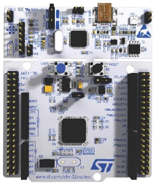
We turn on the peripheral clock for GPIO Port A. We then set pin PA5 as output, which on the STM32F446 board is connected to an onboard green LED.
We then initialize our timer with the tim2_1hz_interrupt_init() function.
Our infinite while loop is empty.
We then have our initialization function.
We first enable the clock for timer 2.
We then set the prescaler value to decrease the 16MHz clock to 10KHz and set the auto-reload value to decreases the 10KHz signal to 1Hz.
We then clear the counter, so that any residual number in there is cleared.
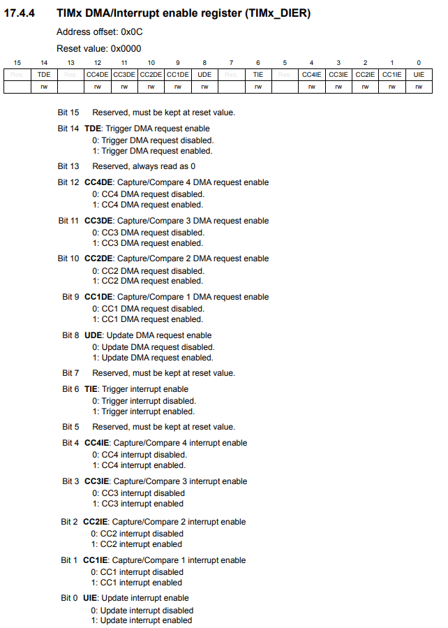
We then enable the TIM2 interrupt by setting the UIE bit, bit 0, to 1. This will enable the update interrupt.
This is shown in the TIMx DMA/Interrupt enable register (TIMx_DIER)
shown below.
We then have to enable the interrupt at the processor side, the Cortex-M4 processor.
In order to do this, we need to look up on the microcontroller datasheet the position of the TIM2 interrupt on the vector table.
Doing this for the STM32F446 microcontroller board, the TIM2 interrupt has a position of 28.
This is important because in the ISER (Interrupt Set-enable register) of the Cortex-M4 procdessor, we are going to have to set bit 28 HIGH in order to enable interrupts for TIM2.
There are a set of registers named the Interrupt Set-enable Registers (ISER), which allow us to enable interrupts.
This is shown below.
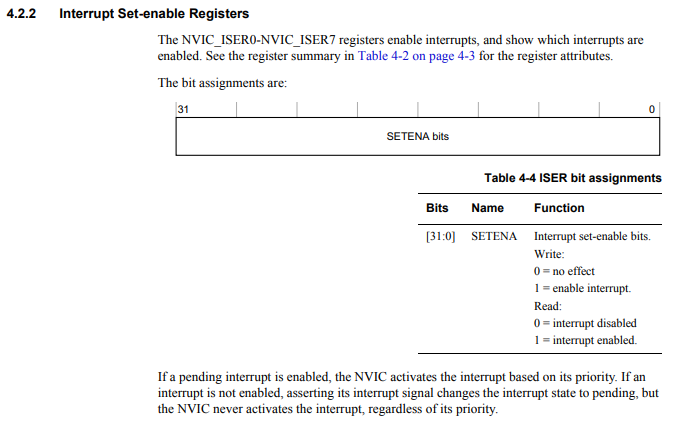
Each register is 32 bits.
Since TIM2 has a position of 28 on the vector table, it will be on the first ISER register, ISER0.
We set bit 28 of this register HIGH by the following line, *pNVIC_ISER0 |= (1 << 28);
We then have our interrupt service routine for timer 2 with the function, TIM2_IRQHandler()
The first thing we do is clear the update interrupt flag. This resets the flag, so
that we can continue the process indefinitely. Every 1 second, a new interrupt is created, which
toggles the LED.
And this is how we can code a timer interrupt driver with an STM32F446 board in C.
Related Resources