
How to Measure a Signal using a Timer in Input Capture Mode in an STM32F446 Microcontroller Board in C
In this article, we show how to measure an incoming signal on a pin by using a timer in input capture mode in an STM32F446 microcontroller board in C.
A pin configured in input capture mode for a given timer listens for some event such as a device to go from OFF to ON, which would be a rising edge. Once detected, it latches the counter value at the event of the edge and will do so for repeated rising edges. This way, we can detect each time a device gets turned ON. By simple equations, we can then compute things desired such as the frequency of the device turning on and its time period (how long it takes for the device to turn back on once turned on).
Input capture mode has strong application for devices such as sensors, to measure the frequency of turn-on's or turn-off's.
In this example project, we will toggle an LED using output capture mode and then connect this pin to a pin configured in input capture mode. We will then configure it to detect every rising edge to determine each time that the LED is turned on.
In order to do this, we utilize 2 general-purpose timers.
Specifically in this project, we utilize timer 2 to be in output capture mode. And we utilize timer 3 to be in input capture mode.
For each of these timers, there needs to be one designed pin that acts as the channel input or output for the timer.
In this project, we choose pin PA5 to act as the output channel for timer 2 (which is configured in output compare mode). This pin has an onboard LED connected to it. With it in output compare mode, we toggle the LED on and off with a 1Hz clock signal. This means that the LED turns on and off every second.
We then take this pin output at PA5 and connect it to PA6, configuring pin PA6 in input capture mode. This way, we can measure whenever the LED turns on by measuring the counter time of each rising edge that occurs.
We create the output compare function and the input capture function completely separate, so that you can see independently how each is set up.
We need 2 major code files in order for this code to work.
We need our header file, which contains many macros and structures that describe the various registers and needed values.
We then need our main C file, which contains the code that puts timer 2 in output compare mode in a toggle state so that it can toggle an LED on and off every 1 second and that puts timer 3
Below is the header file, which we name
stm32f407xx.h
The contents of the main.c file is shown below.
The first thing we must do is include the stdint.h header file and our stm32f446xx.h header file in our main.c file.
After this, we have the prototypes for the 2 functions we will in our program; this tells the compiler the names of the functions, what they return, and the parameter(s) and their types they take in.
We then create a global variable, countercapture, which we set equal to 0.
You will see later in this program that this variable will be used to store the counter value when a rising edge is detected on pin PA5. We'll be able to review this result live as it's occurring.
So next we have our main() function.
We will get to this main() function, but before, we do let's go down to the 2 other functions for the timers. These functions initialize the timers.
Our first timer function, tim2_pa5_output_compare(), places timer 2 in output commpare mode on pin PA5.
We are not going to go in-depth with this timer setup, because we there is a separate article specifically for placing a Timer in Output Compare Mode.
Simply, timer 2 is set up so that it sends a waveform that toggles every 1 second, and this waveform is then sent to pin PA5, which acts as TIM2_CH1 in alternate function mode AF1.
We then have our next function, tim3_pa6_input_capture(), which is the timer function which functions in input capture mode.
We go through this in depth.
We turn on the GPIO Port A peripheral clock, because we are using pin PA6 to act as the timer channel to receive the input capture mode. Or, in other words, this pin will receive the output from pin PA5, when we connect both pins with a jumper wire, so that it can read the counter value of a rising edge in the waveform.
So after turning on the GPIO Port A clock, the next thing we have to do is configure pin PA6 in alternate function mode. To do this, we first set the mode in alternate function mode in the mode register. We then go to the AFRL (Alternate function register low).
But before we configure this register, we should view the Alternate Function Mapping of the GPIO Port A register.
This is shown below.
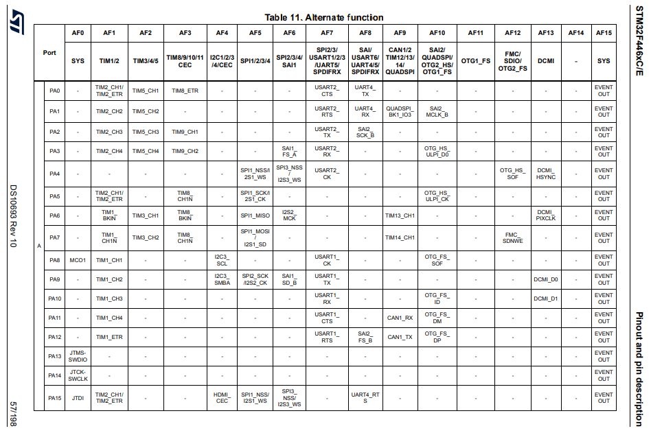
Looking at this map, we can see that PA6 can act as TIM3_CH1 when alternate function mode is configured to AF2. So that is what we need to do. We need to set pin 6 to alternate function mode AF2 in the AFRL register.
This is done in the following line of code, pGPIOA->AFRL |= (0b0010 << 24);
Now that alternate function mode is completely configured, we then have to enable clock access to timer 3.
Timer 3 is connected to the APB1 bus. Specifically timer 3 is bit 1 of the APB1ENR register. Therefore, to enable timer 3, we use the following line, pRCC->APB1ENR |= (1 << 1);
We then set the prescaler value to timer 3. We have the prescaler as the same as the prescaler in timer 2.
Next, we move on to setting the TIMx capture/compare mode register 1, which is a register that allows us to set channel 1 or 2 of a timer as either input or output.
In this case, since we are dealing with TIM3, we need to make its channel which is CH1 set up in input capture mode.
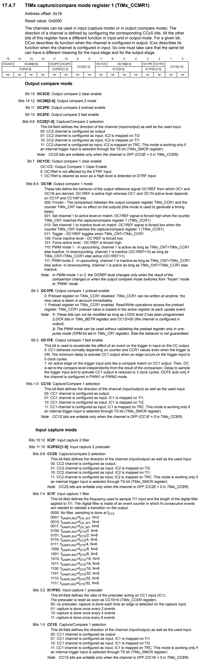
We then set bit 0, the CC1S bit, to HIGH, making the CC1 channel configured as input, IC1 mapped on TI1.
So now channel 1 of TIM3 is in input capture mode.
So after setting up channel 1 of TIM3 to input capture mode, we then have to enable capture mode.
This is done with the TIMx capture/compare enable register (TIMx_CCER), shown below.
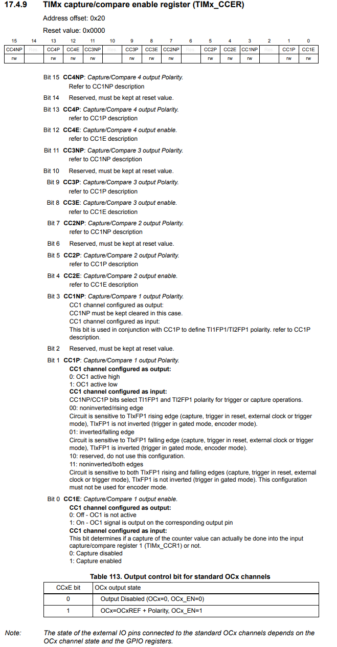
So in order to enable capture mode of CH1 of TIM3, we must set bit 0, the CC1 channel, to HIGH, enabling capture.
We then must enable the timer itself, doing this by setting bit 0, the CEN bit (Counter enable), to HIGH in the TIMx control register 1.
We will now return to the infinite loop of our main function.
What we want to do is we want to ait until the edge is captured, and we can know when the edge is captured by bit 1, the CC1IF bit, of the TIMx status register.
Below is the TIMx status register.
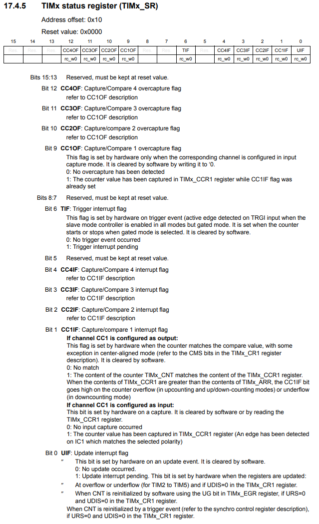
According to the datasheet, if channel CC1 is configured as input, a 0 on this flag indicates no input capture occured. A 1 indicates that the counter value has been captured in TIMx_CCR1 register (An edge has been detected on IC1 which matches the selected polarity).
So we are able to wait until this Capture/compare 1 interrupt flag goes HIGH, through the line, while(!((pTIM3->SR) & (1 << 1)));
As long as the interrupt flag is 0, we stay in the while loop.
Once the interrupt flag is 1, we exit the while loop.
After this while loop, lastly we read the value of the CCR1 register into the variable countercapture.
The CCR1 is the timer capture/compare mode register 1, shown below.
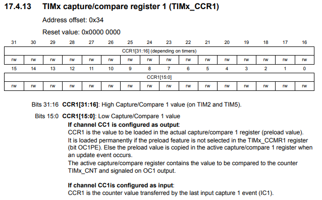
If the CC1 channel is configured as input, which it is in our program, CCR1 is the counter value transferred by the last input capture 1 event (IC1).
So the value of the last counter capture of the last input capture is stored in this
register. We then transfer its value to the countercapture variable.
Now before, we actually compile and run the program, we need to connect pins PA5 and PA6 so that the signal generated in the output compare mode from pin PA5 gets transferred to PA6, which is in input capture mode.
In order to know which pins are which, you need to consult the datasheet for the STM32F446 microcontroller board.
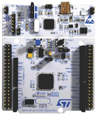
The pinout for the STM32F446RE microcontroller board is shown below.
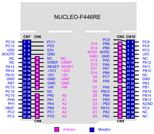
So using this pinout, you can see exactly where pins PA5 and PA6 are located. You must establish electrical connection between them.
We then compile the program and run it in debug mode.
What we want to do is place the countercapture variable in the live expressions section of debug mode.
Once you click Resume on the debug mode, you should see the values of this
countercapture variable updating in real time.
So this is how to measure a singal using a timer in input capture mode
with an STM32F446 microcontroller board in C.
Related Resources