
How to Test a Relay

To test a relay to see whether it is good or defective, the simplest way to do would be to use a multimeter set to the ohmmeter setting and measure various resistance values of the relay.
In this article, we will show what resistance readings you should get when you measure various points of a
relay. By finding the resistance values, we will be able to test a relay to find whether it's good or bad.
Test the Coil Terminals of the Relay with an Ohmmeter
We will start with the coil of the relay.
A relay coil's resistance always comes with the datasheet of the relay. For example, relay coil resistances may be 320Ω, 900Ω, or any of the various resistances. This will come specified with each specific relay used, along with the tolerance of the coil. For example, a relay coil may have a resistance of 320Ω ± 10%. Therefore, the resistance should be anywhere between 288Ω to 352Ω. Therefore, it should read in this range of values when taking the resistance measurement.
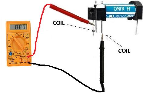
To check the relay coil's resistance, take the multimeter you have and place it in the ohmmeter (Ω) setting and
place the probe leads of the multimeter on the 2 terminals of the relay's coil. It doesn't matter which probe is placed on which
terminals. Resistance isn't polarized.
If you read a value about the rated coil resistance, the coil works and should function correctly. If you read a very low resistance and very high resistance, the coil is either shorted or is open. In this case, since coils normally are not repaired, you must simply replace the relay.
Test the Relay Contacts with an Ohmmeter
Besides the coil terminals, you then can check to see if the the other terminals are good as well. This includes the COM terminal, the Normally Open Terminal, and if the relay is a double throw relay, the Normally Closed Terminal.
The best way to test these contacts is again by measuring the resistance values between them.
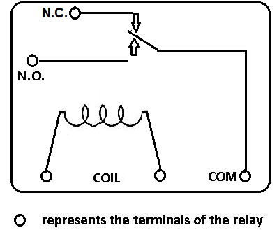
Below is a diagram of a Single Pole Double Throw (SPDT) relay:
How To Test the NC (Normally Closed) Terminal of a Relay
The relay's Normally Closed Terminal should read near 0Ω from the NC (Normally Closed) terminal to the COM (common) terminal, when the relay has no voltage going through it. This is because the NC terminal is normally closed, meaning there should be direct continuity from the NC terminal to the COM terminal when the relay isn't energized; thus, there is almost 0Ω resistance between the 2 terminals.
Take out a multimeter and place it in the ohmmeter (Ω) setting. Place one probe on the COM terminal and the other probe on the NC Terminal. Make sure that you read a resistance of near 0Ω. If you do, then the NC Terminal reads the correct resistance and should function properly.
How To Test the NO (Normally Open) Terminal of a Relay
The relay's Normally Open Terminal (in double throw relays) should read a very high impedance (several megohms (MΩ)) from the NO (Normally Open) terminal to the COM terminal. This is because the NO terminal is normally open, meaning there's no direct connection from the NO terminal to the COM terminal when the relay isn't energized; thus, there is an extremely high impedance between the 2 terminals.
Take out a multimeter and place it in the ohmmeter (Ω) setting. Place one probe on the COM
terminal and the other probe on the NO Terminal. Make sure that you read a high resistance of several megohm (MΩ). If you do, then
the NO Terminal reads the correct resistance and should function properly.
These are the basic, simple but highly effective tests that you can perform on a relay to see if it is good
or not.
Related Resources
Relay Terminals
Relay Wiring Diagrams
How to Connect a Relay to a Circuit