
How You Can Build Your Own Talking Toy
In this project, we will go over you can build your own talking toy.
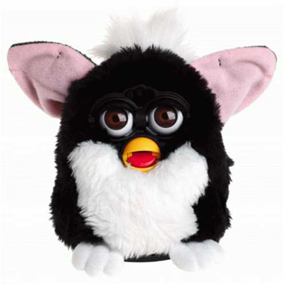
You've probably seen many of these toys. They've been around for years, from the talking tickle me elmo to the talking furby, like the one shown above. How do these devices do what they do when you perform an action such as tickle them or press a certain part of them? How do they talk? In this article, we will go over how you can build a circuit which talks.
The central and most important part of the circuit we build is the chip which allows to preprogram phrases and then play them back when the time is needed.
The chip we will use is a Speakjet chip by Magnevation.
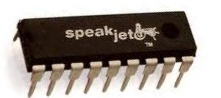
The speakjet is a sound synthesizer chip which allows you to record sounds and then play back the prerecordered sounds. This is why they work perfectly to create devices such as talking toys.
How it works is you connect this IC to a computer, and the chip comes with software so that you can program it to record the sounds which you want. The computer will generate the electrical signals onto the chip of the recorded sayings. These signals correspond to the words, sounds, which form the create the sentences, music, or sound effects of the audio you want. The speakjet chip allows you to program eight sounds; each sound is controlled and can be played back by one of the pins 1-4 and 6-9 of the IC.
You can program the chip to say another phrase such as "Tickle me!", "Hello!", "How are you?" or anything that you'd like.
In the project we'll be doing, the circuit will activated when you touch a specific part of it. So it will be touch-activated. Just like the tickle me elmo, when you press a certain part of the talking toy, it will activate the toy to utter the sound(s) which it is programmed to.
Besides the speakjet synthesizer chip, two other major components we will need in this circuit are an amplifier and a speaker. The amplifier is to increase the audio signal from
the synthesizer to loud enough so that the speaker can play it back. And we need speakers to play out the sound from the speakjet synthesizer chip.
Talking Toy Circuit
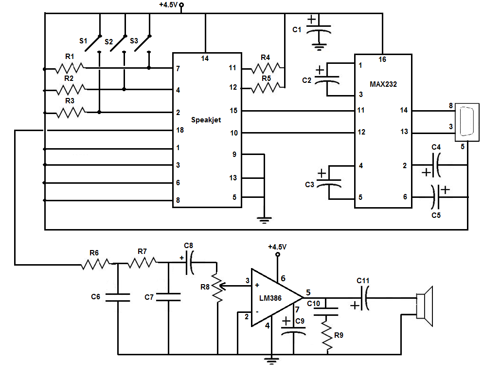
This is the circuit below which we are going to build:
This project was taken from
Electronics Projects For Dummies and slightly modified to be a little simpler to assemble.
The above circuit may seem complex, but we will break the circuit down piece by piece in this article.
The parts which make up the circuit are:
- 5 1KΩ Resistors- These resistors are for R1, R2, R3, R4, and R5. Resistors R1, R2, and R3 limit the current running to ground when you press switches S1, S2, and S3.
- 2 33KΩ Resistors- These resistors are for R6 and R7. Resistors R6 and R7 are two resistors used with capacitors C6 and C7 which form filters (low pass filters) that eliminate high-frequency noise prior to the signals reaching the amplifier.
- 1 10 KΩ Potentiometer- This is for potentiometer R8. R8 is a potentiometer which controls the sound volume of the circuit.
- 1 10Ω Resistor- This is for resistor R9.
- 2 0.01µF ceramic capacitors- This is for capacitors C6 and C7. Capacitors C6 and C7 are two capacitors used along with resistors R6 and R7 that form low-pass filters that eliminate high-frequency noise prior to the signals reaching the amplifier.
- 5 1µF tantalum or electrolyic capacitor- These are for capacitors C1, C2, C3, C4, and C5. C1 is a capacitor which filtes noise from the +4.5V DC power source line to the Max232 chip. C2, C3, C4 and C5 are capacitors that fill a function that the Max232 designers call charge pump capacitors. These are required to make the Max232 chip function properly.
- 1 0.047µF ceramic capacitor- This is for capacitor C10. This capacitor acts as a current bank for the output of the LM386 chip. This capacitor drains when sudden surges of current occur and refills with electrons when the demand for current is low.
- 2 10µF electrolytic capacitors- This is for capacitors C8 and C9. C8 is a capacitor that removes any DC offset from the output of the SpeakJet synthesizer chip. It is a coupling capacitor. C9 is a capacitor that improves the stability of the LM386 amplifier to prevent problems such as oscillation.
- 1 100µF electrolytic capacitor- Ths is for capacitor C11. C11 is a coupling capacitor which removes any DC offset from the output of the LM386 amplifier.
- Battery Pack for 3 AAA Batteries- This is to hold the 3 batteries to supply the 4.5V needed in this circuit. If you are using a DC power supply, then you don't need this battery pack.
- Speakjet Sound Synthesizer Chip- As discussed, this is one of the main chips which allows to record phrases or sound effects.
- MAX232 driver/receiver Chip- This chip allows us to convert the signals from your computer. The signals aren't generated from your computer wtih the correct voltage which is needed by the Speakjet chip, so the signals from your computer needed to be converted, so that they can be used by the Speakjet chip. This chip also converts signals from the Speakjet into signals that your computer can use.
- LM386N-1 Amplifier Chip- This chip is the amplifier which amplifies the sound enough from the speakjet chip so that it can be played out by speakers.
- 8 ohm, 1 watt speaker- This is the speaker which plays out the sounds which we program the speakjet synthesizer chip to.
- 3 SPST switches- This is for switches S1, S2, and S3. Switches S1, S2, and S3 control the voltage on pins 2, 4 and 7 on the speakjet synthesizer chip. The switches are normally open, which means each pin is normally connected to ground. When the switch is pressed down, the voltage on the corresponding pin raises to +4.5 volts. When you release the switch, the voltage on the pin returns to ground. In this project, we program the speakjet to trigger (and say its phrases when the voltage on a pin changes from high to low (+4.5V to ground). So since we have 3 switches, our toy can say three distinct phrases. We could use up to 8 sounds, since the speakjet synthesizer chip allows it, but in this project, we only do 3 to simplify the process.
- DB9 Connector- A DB9 Connector port is used so that we can program the SpeakJet chip. The SpeakJet is programmed through serial connection. We take a serial connector from the computer and then plug it into the port on the circuit board. Thus, we can program the chip through serial data. This is how the computer will program the chip. In this circuit connection, we connect to pins 3, 5, and 8 of the DB9 connector.
Program the Sounds to the SpeakJet Chip
The first thing we have to do is program the SpeakJet Synthesizer chips the sounds which we want the toy to say. For this to occur, have the above circuit set up. You will need the DB9 connector from the circuit in order to form a serial connection with the computer to program it. And you will need the Max232 chip to convert the signals to the correct levels for the SpeakJet chip, so it's best to have the complete circuit all connected to proceed.
The SpeakJet has a lot of built-in sounds, including 72 speech elements, 43 sound effects, 3 octaves of musical notes and 12 touch tones. By mixing and matching these and controlling the pitch rate, bend, and volume settings, you can produce many differet sounds, phrases, and musical tones.
You can either have the option of assigning premade sounds to the circuit, or you can even create your own sounds and words.
If you want to learn more about the SpeakJet, including how to program it, listening to samples from it, visit the SpeakJet Homepage where you can find a lot of information from the producer, Magnevation.
If you want to see the datasheet for the SpeakJet, visit this resource: SpeakJet Datasheet/Manual.
How the Circuit Works
Once the sounds have been programmed successfully, we can disconnect the computer serial connector from the circuit. During circuit operations, this can be left open. The only purpose of the serial connection was to program the chip.
For the circuit to work, all you have to do is press down either of the tactile switches, S1, S2, and S3. Based on how you programmed the chip, a new sound should be heard after each press, if you programmed distinct sounds for each of the pins.
Now you can enclose this circuitry inside of any toy or muffet that you want. Strategically place the tactile switches in any part of the toy which you want to speak a sound when that part is pressed. For example, for each of the 3 sounds for this circuit, you can place a switch in the hand of toy, in the stomach of the toy, and one in the leg of the toy. You can choose. To make sure that each can reach the various parts where you want to incorporate them, you can just increase the length of the jumper wire to get the switch anywhere you would want it.
This is how talking toy electronics works and how you can build your own and incorporate it into any type of toy. It does require a lot, but if you have the drive, then you'll
do it.

Related Resources
How to Build a USB-powered Device
How to Build a DC Motor Circuit
How to Build a Speaker Circuit with Adjustable Volume
How to Build a Simple Microphone circuit
How to Build a Touch Sensor Circuit