
How to Build a Latch Circuit with Transistors
In this circuit, we will build a latch circuit using transistors.
So if you don't have an SCR available, which is a device which function as a latch, then you can build a latch yourself with transistors.
A latch is a device that is like a transistor. It has 3 terminals just like a transistor which function as a base, collector, and emitter. The only difference between a transistor and a latch is that once sufficient current is fed into the base terminal, current permanently flows from the collector to emitter. In a transistor, current flows only across the collector to emitter when sufficient current is fed into the base. The latch is different. When sufficient current is fed once into the base, it permanently conducts current from the collector to emitter, even if the current at the base is removed. It's a latch. The only way to shut off the circuit and reset it is by removing the supply voltage.
Latches function well and are used frequently in alarm circuits. If triggered once, the sirens will flash indefinitely or the buzzer will sound indefinitely until someone manually removed the power.
In this circuit, we will use 2 transistors to form a latch. These are the BC547 transistor and the BC557 transistor.
It will be explained in detail how this circuit works below.
Components
- BC547 NPN transistor
- BC557 PNP transistor
- 3 2.2KΩ resistors
- 1KΩ resistor
- 330Ω resistor
- LED
- Power source
The BC547 is a BJT NPN transistor.
The BC547 can handle a maximum voltage of 65V at its collector.
The datasheet for the BC547 can be found at the following link: BC547 NPN Transistor Datasheet.
The BC557 is a BJT PNP transistor.
The BC557 can handle a maximum voltage of 65V at its emitter.
The datasheet for the BC557 can be found at the following link: BC557 PNP Transistor Datasheet.
The resistors serve for biasing purposes.
In this circuit, we will latch on an LED.
Transistor Latch Circuit
The latch circuit we will build using transistors is shown below.
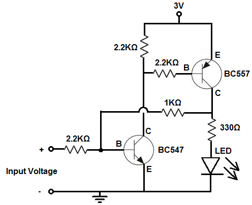
So, for this circuit, the first transistor is the BC547 while the second is the BC557.
So the first 2.2KΩ resistor that goes into the base of the BC547 is used to limit current that goes to the BC547. You always need resistors for the bases of BJT transistors. If you do not use resistors and resistors that have enough resistance, you can fry transistors. And it's pretty easy to do. When feeding current into the base of a transistor, you have to limit the current entering the base. So, again, this 2.2KΩ resistor limits current going into the BC547 transistor.
The 2.2KΩ resistor at the very top of the circuit functions as a pull-up resistor, giving 3V of power to the collector of the BC547 and to the emitter of the BC557.
The other 2.2KΩ resistor at the base of the BC557 limits the current flow out of the BC557, which flows into the collector of the BC547 transistor.
The 1KΩ resistor is used to limit current going into the base of the BC547 from the output of the BC557.
There are 2 possible currents being fed into the base of the BC547 transistor. There is the current produced from the input voltage source, VIN. And then there's current fed into the BC547 from the output of the BC557. The first current from the input voltage source is needed to trigger on the latch circuit. And the current from the output of the BC557 being fed into the BC547 is needed to keep the circuit latched on. The BC547 provides the continouous current to the base of the BC547 so that it continually stays on, once it's initially fed on by the input voltage source.
The LED along with the 330Ω resistor are the output of the circuit. The 330Ω resistor limits current
to the LED so it doesn't blow.
How the Circuit Works
This is how the latch circuit operates.
When 0.65V is fed into the base of the BC547 transistor, it turns on. Once it turns on, current flows from VCC down to the base of the BC557 transistor. This, in turn, turns on the BC557 transistor. Current now flows from the collector of the BC557 in 2 directions. Some of the current flows to turn on the load, which in this case is the LED. And some of the current flows into the base of the BC547 transistor. This is really how the latch is formed. Once we turn on the BC547, it, in turn, turns on the BC557. And then the BC557 provides continuous current to the base of the BC547, so that it remains on, even if we turn off the input voltage supply, VIN. The only way to turn off the circuit and reset it, then, is to turn off the supply voltage VCC. Turning off the input voltage, VIN will have no effect. Once we turn it on the input voltage once to the threshold voltage of 0.65V, which is the voltage needed to turn on the BC547, it's latched on.
So this is how a latch circuit can be built with transistors.
It perfectly mimics an SCR, a silicon-controlled rectifier.
It functions as a digital latch.
And it can be used well for alarm circuits. It has many practical uses.
To see a demonstration of this circuit in real life, see the following video shown below.
Related Resources
How to Build an Inverter Circuit with a Transistor