
How to Build an Inverter with a Transistor
In this circuit, we will build an inverter with a transistor.
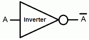
An inverter is a component or device that inverts the state or logic level of a signal to the opposite logic level.
Thus, if a LOW signal is fed into an inverter, it flips it to a HIGH isgnal.
If a HIGH signal is fed into an inverter, it flips it to a LOW signal.
So an inverter changes the logic state to the opposite logic of what is fed into it.
There are many ways of creating inverters, including with any type of logic chip. You can create an inverter with AND gates, NAND gates, OR gates, NOR gates, and pretty much all the gates by combining them in the correct fashion to produce an inverter. You can create an inverter directly wtih an inverter chip. These are composed of inverter or NOT gates. Or you can create an inverter with a transistor.
In this circuit, we will create an inverter with a transistor.
We will show exactly how this works in detail below.
Components
- 2N700 MOSFET transistor
- 1MΩ resistor
- Jumper Wire
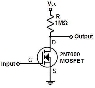
The 2N7000 is an N-channel MOSFET.
It has 3 leads, the the source, gate and the drain.
The input signal attaches to the gate of the transistor. This is the input signal that we want the transistor to invert.
We place a 1MΩ resistor on the drain terminal. The drain also must get a positive voltage. The 2N7000 MOSFET can handle up to 60V at the drain terminal. To this drain terminal, underneath the resistor, we place an output jumper wire. This jumper wire will carry the inverted output voltage signal.
We connect the source terminal directly to ground. -
Transistor Inverter Circuit
The inverter circuit we will build with a transistor is shown below.
The breadboard schematic of the circuit above is shown below.
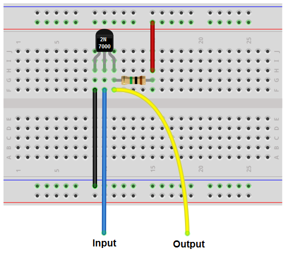
So this is just a basic inverter circuit built using a MOSFET transistor.
Whatever signal we feed into the input gets inverted to the opposite logic state at the output.
This is how it works.
When a very low voltage or no voltage at all is fed into the gate terminal of the transistor, it is not enough power to turn on the transistor. Therefore, no current can flow across the transistor from the drain to the source. When this happens, all the voltage is built up across the resistor. Therefore, if we place a jumper wire underneath the resistor, in this condition, all the voltage from VCC will fall across the 1MΩ resistor.
Another way to understand this or another perspective to take on this, is to consider ohm's law. Ohm's law states that, voltage= current * resistance (V= IR). In order, for there to be voltage across the transistor, it must pass current through it. If it doesn't, there can be no voltage across it. Therefore, if the voltage going to the gate is insufficient or nonexistent, the transistor isn't triggered on. Therefore, no current can pass through. Since current is 0mA, then this means that the voltage across the transistor 0V (since V=IR). Therefore, all the voltage falls across the 1MΩ resistor. This is why when the voltage is LOW or 0V at the gate, the jumper wire will be HIGH at the value of VCC.
Now, the opposite scenario, when enough voltage is fed into the gate, a HIGH voltage, then this is enough to power on the transistor. The transistor can now conduct current across from the drain to source. Now the voltage is no longer concentrated across the resistor. It's concentrates mostly on the transistor. So as you increase the voltage going into the gate, it allows a greater current to flow through. The voltage at the output jumper wire decreases. Now there will be a LOW voltage at the output jumper pin.
The resistor at the drain terminal functions as a pull-up resistor. It pulls the voltage at the drain terminal up to VCC. So whatever voltage VCC is at, the resistor will contain when a LOW voltage signal or no voltage is fed into the gate.
If we give VCC a voltage of 12V and have 0V at the gate of the transistor, then there will be about 6V at the output pin. As we turn up the voltage at the gate from 0V to a hgiher voltage, then the voltage at the output pin falls. If we increase the voltage at the gate to about 6V, half of VCC, then the voltage at the output pin falls to less than 1V, about 0.6V. So you can see the dramatic difference in voltage output from when the gate is 0V (OFF or LOW) to when the gate voltage is 6V. The voltage output goes from 6V to 0.6V. If we add a switch to the gate of the transistor with 6V feeding it, while 12V is feeding the drain, the it really functions as an inverter, with an output of 6V when the gate voltage is 0V and an output of 0.6V when the gate voltage is 6V.
You could then feed this output pin into any device that can read or use the voltage such as a voltage comparator or a logic IC.
And this is how an inverter can be built with a MOSFET transistor.
Related Resources
How to Build a Latch Circuit with Transistors