
How to Build a CAN Transceiver Circuit with an MCP2551 Chip
In this project, we will build a CAN transceiver circuit with an MCP2551 chip.
A CAN transceiver circuit is a circuit that can communicate with the CAN bus and extract data from it. Multiple electrical subsystems can connect to the CAN bus and each can communicate with the microcontroller or CAN chip connected, though not at the same time. This allows the microcontroller to analyze data from all of these units and respond accordingly to the data and which subsystems are priority. It's a message-based communication system between the microcontroller and all the electrical subsystems on the CAN bus.
A CAN bus stands for Controller Area Network bus. It is a type of communication hub in which many devices, or nodes, can be connected up to it. It is a message-based protocol, a type of multiplex electrical wiring system.
The CAN bus is used in many applications, the most common being in automobiles. Many cars are equipped with a CAN bus and exchange messages through this bus.
The CAN is an International Standardization Organization (ISO) defined serial communications bus originally developed for the automotive industry to replace the complex wiring harness with a two-wire bus. Devices connected to a CAN bus do so via 2 wires, CANH (CAN HIGH) and CANL (CAN LOW), two simple connections. Another reason it was created is because it provides higher immunity to electrical interference than a typical pure digital signal. A car is a complex machine that has numerous components that can create signals that may interfere with digital systems. These signals can transpose onto signals of a digital system and create unintended effects. Therefore, a communication system was needed that gave high immunity against interfere. The CAN bus provides this so that there is less interference with the car's digital systems. It is much more adept at doing this than a pure digital waveform.
The 1988 BMW 8 Series was the first production vehicle to a feature a CAN-based multiplex wiring system.
The CAN bus is one of five protocols used on-board diagnostics (OBD)-11 vehicle diagnostics standard.
Today, it is very popular in many new cars. Acuras is one example of a car company that widely uses them.
Cars, in general, are adopting more electronic systems. As this grows, so does the uses of using a CAN bus so that these devices can communicate with a
microcontroller.
Components Needed
- MCP2551 CAN Transceiver Chip
- Microcontroller or CAN Controller
- 10KΩ resistor
The MCP2551 is a CAN transceiver chip. It is capable of reading data from a CAN bus and transmitting and receiving data from a microcontroller or CAN controller.
The datasheet for the MCP2551 can be found at the following link: MCP2551 CAN Transceiver Datasheet.
The MCP2551 is an 8-pin chip.
The pinout for the chip is shown below.
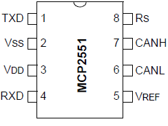
The Rx pin, pin 4, is the receiver pin. It receives the data from the CAN bus. It reflects the differential bus voltage between CANH and CANL. If the differential voltage is LOW, this corresponds to a dominant state. If the differential voltage is HIGH, this corresponds to a recessive state. So the Rx pin is able to receive data from the CAN bus so that interpretation can be made.
The CANL, CAN LOW, pin, pin 6, is the pin that represents the low side of the CAN differential bus. It is connected to one of the inputs of the internal comparator inside the chip.
The CANH, CAN HIGH, pin, pin 7, is the pin that represents the high side of the CAN differential bus. It is connected to the other input of the same internal comparator chip as the CANL pin. By both the CANH and CANL pins being connected to the comparator chip, the differential voltage between the 2 pins can be measured. If the differential voltage is 0, this represents a dominant state by the particular node the chip is reading from. If the differential voltage is 1, this represents a recessive state.
The RS pin, pin 8, is the slope resistor input. This pins is used to select high-speed, slope-control, or standby mode based on the external biasing resistor.
When in high-speed mode, the transistor output drivers have fast output rise and fall times to support high-speed CAN bus rates. High-speed mode is selected by connecting the RS pin to V SS.
Slope-control mode further reduces electromagnetic interference (EMI) by limiting the rise and fall times of CANH and CANL. The slope, or slew rate, is controlled by connecting an external resistor between RS and ground. The slope is proportional to the current output at the RS pin.
The last mode is the standby, or sleep, mode. In sleep mode, the transmitter is switched off and the receive pin operates at a lower current. The receive pin still is functional, only operating at a slower speed.
VREF, the reference voltage, pin, pin 5, is equal to VDD/2. We don't use it in
our circuit, so we leave it unconnected.
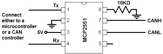
MCP2551 CAN Transceiver Circuit
The circuit to build a CAN transceiver circuit using an MCP2551 chip is shown below.
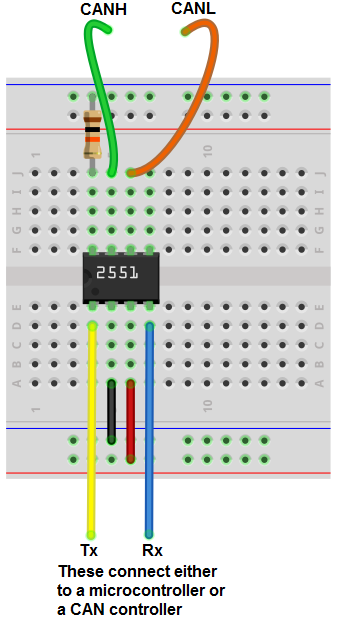
The breadboard of the circuit above is shown below.
To power on the MCP2551 CAN transceiver chip, we connect VDD, pin 3, to 5V and we connect VSS, pin 2, to ground. The maximum voltage that the chip can receive is 7V, so 7V should not be exceeded. 5 volts supplies sufficient power for the MCP2551 to be able to operate.
The CAN-compatible device that you want to add to the CAN bus connects to the CANH and CANL pins. A CAN-compatible device has 2 terminals, a CANH and a CANL. You connect the CANH terminal of the device to the CANH terminal of the MCP2551 and the CANL terminal of the device to the CANL terminal of the chip. All devices that you want to connect to the CAN bus are connected to the CANH and CANL lines. Up to 112 nodes can be connected to the CAN bus.
How it works is that the CANH and CANL lines are connected to the inputs of an internal comparator of the chip. These comparators measure the inputs and are able to give us the differential voltage output of the 2 signals. If the differential output is 0V, then the signal is said to be dominant. If the differential voltage is greater than 1V, then the signal is said to be recessive.
The output of this signal, the differential signal, is output through the Rx pin, pin 4. This differential voltage is then transmitted either to the CAN controller or microcontroller for analysis.
After the signal is analyzed by the microcontroller/CAN controller, it is then sent out from the Tx pin to the MCP2551 transceiver chip. So the Rx pin outputs the differential voltage to the microcontroller and the microcontroller outputs the analyzed signal through the Tx pin back to the MCP2551. This is why the chip is a transceiver. It sends out and receives data.
To reduce EMI emission in the circuit, we connect the RS pin, pin 8, to a resistor connected to ground. A resistor of about 10KΩ suffices well. This prevents further EMI.
And this is all that is required for connecting the hardware of a CAN transceiver chip.
Programming the chip, on the other hand, is a completely different story and is much harder. These is because there are many components of the code to understand. There are identifier bits, error bits, understanding of priority, different formats, and more to deal with.
Programming the chip requires a lot of in-depth knowledge about what exactly occurs during the entire receive/transmit process. You must also be able to decode the entire message for data transmission, which requires a good deal of knowledge.
Again, CAN bus communication is a standard today. If you know the schematic diagram of the electronics housed in a car, you can access the data on this CAN bus system using a CAN
transceiver chip and connect it to a micrcontroller to get data from electrical subunits of the car to a microcontroller for processing. This can allow you to tap into the data and perform
whatever actions you need based on it.
Related Resources