
How to Control a 4-digit 7-segment LED Display with a Max7219 Chip
In this circuit, we will show how to display numerals on a 4-digit 7-segment display using a Max7219 chip.
The Max7219 is an 8-digit LED display driver, meaning it can connect to and control as many as 8 digits.
In this circuit, we're simply going to control a 4-digit 7-segment display, however.
Components
- Max7219 Chip
- 4-digit 7-segment LED display
- 40KΩ resistor
- 10μF capacitor
- 100nF capacitor
The Max7219 is a 8-digit LED display driver, meaning it can drive up to 8 digits. It can be obtained very cheaply from a number of online retailers for under $1 on ebay.
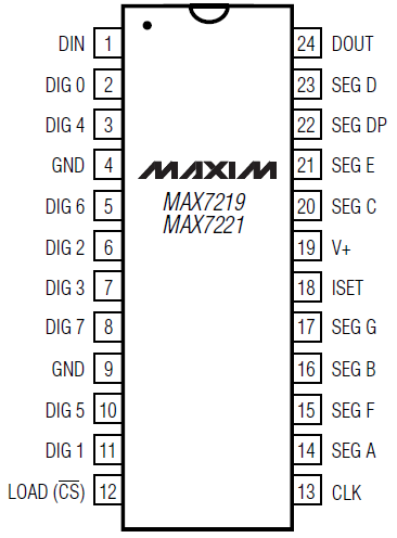
The pinout of the Max7219 is shown below, so that you can see how to
connect it in the circuit.
Just so that you can have a frame of reference, we show the pinout of a 4-digit 7-segment LED display below.
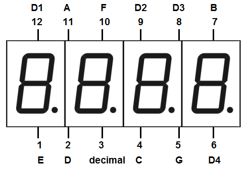
A 4-digit 7-segment LED display has 12 pins. 8 of the pins are for the 8 LEDs on a 7 segment display, which includes A-G and DP (decimal point). The other 4 pins represent each of the 4 digits from D1-D4.
The Max7219 pinout should make a lot more sense now.
The Max7219 needs about 5V to operate. So we connect V+, pin 19, to 5V and the ground pins, pin 4 and 9, to ground. We don't just connect the 5V to ground. We connect 2 capacitors in parallel to ground. This includes a 100nF capacitor and a 10μF capacitor. This helps filter out noise from the power supply and to make sure the power supply is steady.
All of the seg pins connect to the corresponding segment on the 7-segment LED display. So Seg A connects to the A pin on the 7 segment LED display. Seg B connects to B. Seg C connects to C and so on until you connect all the way to Seg G and DP. This covers 8 connections.
Now we connect the digits. Just like with the segment connections, the digits on the Max7219 connect to the corresponding digits on the 7 segment LED display. Digit 0 on the Max7219 connects to pin 12 on the 4-digit LED display, which is D1. Digit 1 on the Max7219 connects to D2. Digit 2 connects to D3. Digit 3 connects to D4.
The Max7219 works on in synchrony with the microcontroller it is connected to on a clock signal. On the rising edge of the clock signal are commands and instructions executed. So the clock pin of the Max7219, pin 13, connects to digital pin 13 of the arduino. This way, the microcontroller and the Max7219 can operate in synchrony.
The ISET pin is the pin that allows us to set the current that is output to the digit and segment pins. These are the pins that supply current to the output device, which in this case is a 4-digit 7-segment display. We set ISET through the use of an external resistor connected to V+. Being that we want about 10mA of current to be supplied to the 7-segment LED display, we use a 40KΩ connected to V+.
The DIN pin, pin 1, of the Max7219 connects to pin 11 of the arduino. Pin 11 of the arduino is the MOSI pin, which stands for Master Out Slave In. This is the pin which allows the arduino to communicate and send data to the Max7219 chip. In this circuit, there is only one-way communication between the microcontroller and the Max7219 chip. The arduino simply needs to send instructions to the Max7219 chip on how to control the output device without the Max7219 chip needing to send data to the micrcontroller.
The load/
The DOUT is left unconnected. This is used if we are daisychaining multiple Max7219 chips together.
Max7219 4-Digit 7-Segment LED Display Driver Circuit
The 4-Digit 7-Segment LED display driver circuit we will build using a Max7219 chip is shown below.
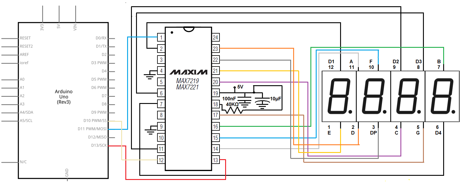
So we have 5V connected to V+ and connected to ground through a 100nF ceramic capacitor and a 10μF electrolytic capacitor.
To set the current output from the output pins, which will feed our output device, we connect a 40KΩ resistor to V+. This allows for about 10mA of current outflow.
We connect all the digits and segments, as they correspond on the Max7219 and the microcontroller.
We connect DIN, pin 1, to D11 on the arduino.
We connect the clock pin, pin 13, to digital pin 13 on the arduino.
We connect the slave Select or Chip Select (
This establishes all the hardware connections.
Next, we just now need the code in order for this circuit to operate.
Code
This code displays a number from 0 to 9999 on a four-digit display.
#include <SPI.h>
const int slaveSelect= 10;
const int numberofDigits= 2;
const int maxCount= 99;
int number=0;
void setup()
{
Serial.begin(9600);
SPI.begin();
pinMode(slaveSelect, OUTPUT);
digitalWrite(slaveSelect, LOW);
sendCommand (12,1);
sendCommand (15,0);
sendCommand (10,8);
sendCommand (11, numberofDigits);
sendCommand (9, 255);
digitalWrite(slaveSelect, HIGH);
}
void loop(){
if(Serial.available())
{
char ch= Serial.read();
if (ch == '\n')
{
displayNumber(number);
number=0;
}
else
number= (number * 10) + ch - '0';
}
}
void displayNumber (int number)
{
for (int i=0; i < numberofDigits; i++)
{
byte character= number % 10;
if (number == 0 && i > 0)
character = 0xf;
sendCommand(numberofDigits-i, character);
number= number/10;
}
}
void sendCommand(int command, int value)
{
digitalWrite(slaveSelect, LOW);
SPI.transfer(command);
SPI.transfer(value);
digitalWrite(slaveSelect,HIGH);
}
This code will display a number between 0 and 9999.
Related Resources
How to Vary the Brightness of an LED
How to Build an LED Driver Circuit
How to Build an LED Flasher Circuit