
How to Build a Modified Window Comparator Circuit
In this circuit, we will show how to build a modified window comparator circuit.
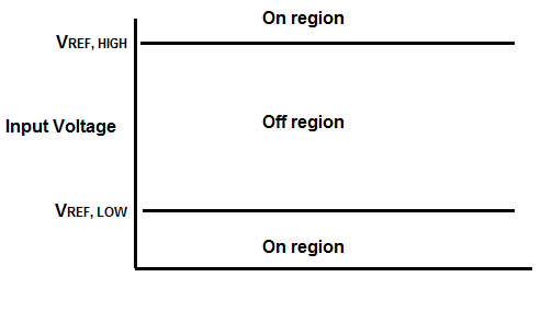
A window comparator is a circuit that operates within a certain frame, or window, of voltage.
In this modified window comparator circuit, the circuit operates outside the window voltage; meaning instead of operating in between the low and high reference voltage range, the circuit operates either below the low reference voltage or above the high reference voltage.
So it's the exact opposite of the window comparator circuit in terms of its operating voltage features. Whereas the window comparator functions in between the low and high reference voltages, the modified window comparator circuit functions below the low reference voltage or above the high reference voltage.
In order to create this modififed window comparator circuit, 2 comparators are needed.
We will use 2 LM741 chips to build our modified window comparator circuit.
We can set any level that we want to for VREF, HIGH and VREF, LOW as long as the comparator can manage those voltages.
This modified window comparator circuit can be used when you don't want a circuit operating within a certain voltage range. The use for this may be more limited than a window
comparator circuit but this modified window comparator still has its uses. An example of its use may be for a voltage-controlled oscillator, where you don't want the circuit oscillating at a
certain frequency. Anything such as that. You can use it according to your imagination.
Components
- 2 LM741 Op Amp Chip
- 2 1N4006 Diodes
- LED
- 470Ω resistor
The LM741 is an general-purpose operational amplifier IC.
The LM741 is an 8-pin chip.
If you want to know all the pinout of the LM741 op amp, what each pin is and what each pin does, see s LM741 Op Amp Pinout.
As a quick runthrough, we will not be using pins 1, 5, and 8 on this chip.
Pin 2 is the inverting terminal and pin 3 is the noninverting terminal. These are the input terminals of the chip.
Pins 4 and 7 are the power pins of the LM741 in order to power it on. Pin 4 is V- and pin 7 is V+. We connect pin 7 to positive voltage and pin 4 to either ground or negative voltage. In this circuit, we connect it to negative voltage.
And, lastly, pin 6 is the output. This is the pin which the output sine wave will come out of.
As far as the diodes go, any 1N400x diode should be sufficient or even any diode, period.
Modified Window Comparator Circuit
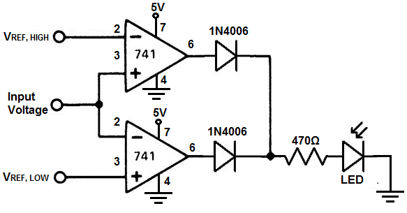
The modified window comparator circuit we will build with 2 LM741 op amp chips is shown below.
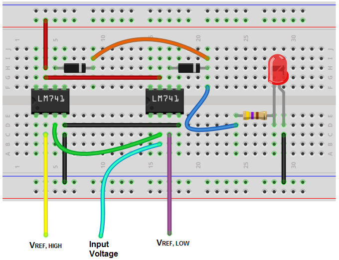
The breadboard circuit of the circuit above is shown below.
So the first thing that should be done is powering of the chips. In order to power the LM741s, we apply +5VDC to V+, pin 7, and we connect V-, pin 4, to ground. This establishes the power we need to operate the LM741.
Now in order to configure this circuit as a modified window comparator, we set the inverting terminal, pin 2, of the first chip as the high voltage reference level. We then take the noninverting terminal on the same chip and connect it to the inverting terminal of the other LM741. For the second LM741, we take the noninverting terminal and connect our low voltage reference level.
The input voltage into the circuit connects to either the noninverting terminal of the first chip or the inverting terminal of the second (since both are tied common, it doesn't matter).
What this configuration does is that any voltage higher than the high voltage reference level will turn the output on as well as any voltage below the low reference voltage.
The diodes maintain the output voltage from the LM741, so they are necessary for this circuit. Without the diodes, the circuit will not work.
To see how this circuit functions in real life, see the following video below.
Related Resources
How to Build a Window Comparator Circuit