
How to Build a Window Comparator Circuit
In this circuit, we will show how to build a window comparator circuit.
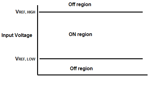
A window comparator is a circuit that operates within a certain frame, or window, of voltage.
Normally how a voltage comparator works when by itself is that when the voltage rises above a certain level at the inverting terminal, the output turns on. Any voltage above this reference level keeps the output on.
However, a window comparator circuit creates a sandwich effect, in that if the voltage rises above a certain level called the VREF,LOW level, it turns on but if it rises above the VREF, HIGH level, it turns off. So the output is only on for voltages in between the low and high reference voltage levels that we set.
This is a window comparator, because the output only turns on when the input voltage is within this window of voltage.
In order to create a window comparator circuit, 2 comparators are needed.
We will use 2 LM741 chips to build our window comparator circuit.
We will also use an additional 4049 inverter chip.
We can set any level that we want to for VREF, HIGH and VREF, LOW as long as the comparator can manage those voltages.
Window comparators can be used for any circuits that you want operating within a given range of voltages only. For example, the lower limit of the voltage range may be the minimum
voltage needed for the circuit to operate. The upper limit of the voltage range may represent the maximum voltage that you want the circuit exposed to due to maybe sensitive components. So
the window comparator has its uses.
Components
- 2 LM741 Op Amp Chip
- 4049 inverter chip
- 2 1N4006 Diodes
- LED
- 470Ω resistor
The LM741 is an general-purpose operational amplifier IC.
The LM741 is an 8-pin chip.
If you want to know all the pinout of the LM741 op amp, what each pin is and what each pin does, see s LM741 Op Amp Pinout.
As a quick runthrough, we will not be using pins 1, 5, and 8 on this chip.
Pin 2 is the inverting terminal and pin 3 is the noninverting terminal. These are the input terminals of the chip.
Pins 4 and 7 are the power pins of the LM741 in order to power it on. Pin 4 is V- and pin 7 is V+. We connect pin 7 to positive voltage and pin 4 to either ground or negative voltage. In this circuit, we connect it to negative voltage.
And, lastly, pin 6 is the output. This is the pin which the output sine wave will come out of.
The 4049 is a hex inverter chip, meaning it is composed of 6 inverters.
In this circuit, we will simply be using 1 inverter. The first inverter's input is pin 3. The inverter's output is pin 2. In order to power the chip, we supply 5V to pin 1 and we ground pin 8. So all we are using are 4 pins on the inverter chip.
As far as the diodes go, any 1N400x diode should be sufficient or even any diode, period.
Window Comparator Circuit
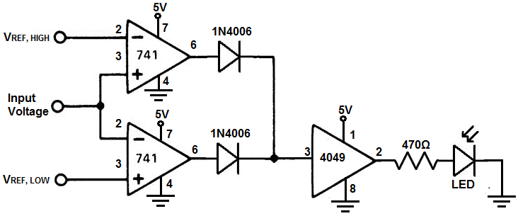
The window comparator circuit we will build with 2 LM741 op amp chips and an inverter chip is shown below.
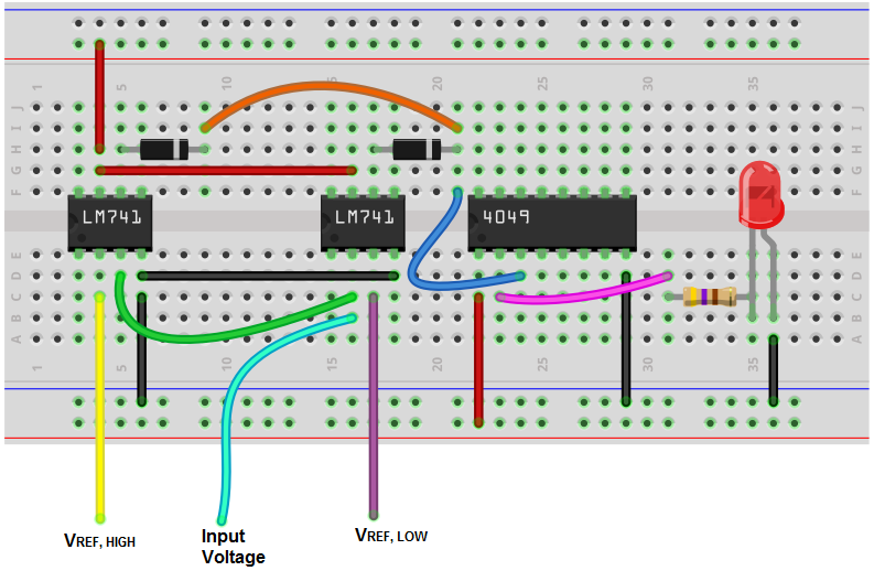
The breadboard circuit of the circuit above is shown below.
So the first thing that should be done is powering of the chips. In order to power the LM741s, we apply +5VDC to V+, pin 7, and we connect V-, pin 4, to ground. This establishes the power we need to operate the LM741.
To power on the 4049 inverter chip, we apply +5VDC to pin 1 and we ground pin 8.
So all our chips have operating power.
Now in order to configure this circuit as a window comparator, we set the inverting terminal, pin 2, of the first chip as the high voltage reference level. We then take the noninverting terminal on the same chip and connect it to the inverting terminal of the other LM741. For the second LM741, we take the noninverting terminal and connect our low voltage reference level.
The input voltage into the circuit connects to either the noninverting terminal of the first chip or the inverting terminal of the second (since both are tied common, it doesn't matter).
What this configuration does is that any voltage higher than the high voltage reference level will turn the output on as well as any voltage below the low reference voltage.
For a window comparator, we want the exact opposite. We want the output on when the voltage is between the low and high reference voltage. Therefore, in order to create this, we hook up the output of this circuit to an inverter.
The 4049 is a very popular and commonly used inverter chip. Therefore, we attach the output of from the LM741 into the input of the inverter chip. This will give us a classic window comparator circuit.
The diodes maintain the output voltage from the LM741, so they are necessary for this circuit. Without the diodes, the circuit will not work.
One thing you may ask is why the LM741 isn't configured so that the inverter isn't needed. It seems like if you make the noninverting terminal of the first LM741 the high voltage reference level and the inverting terminal of the second LM741 the low voltage reference, the inverter for the circuit wouldn't be necessary. And the answer is, the circuit was built but didn't work.
The above circuit is the only circuit we were only to build of a window comparator that was proven to work. More analysis and circuitbuilding will be done to try to improve
the simplicity of the circuit. But for now, the circuit above is the only true window comparator circuit.
To see how this circuit functions in real life, see the following video below.
Related Resources
How to Build a Modified Window Comparator Circuit