
How to Build a Hall Effect Sensor Circuit
In this project, we go over how to build a hall effect sensor circuit.
A hall effect sensor is a sensor which detects magnetic fields. With this circuit, we will be able to detect when any mangets in proximity of our circuit.
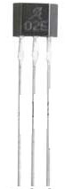
The hall effect sensor we will use in this circuit is an A1302 hall effect sensor manufactured by Allegro. This IC can detect magnetic fields. We will then connect this IC to an arduino, so that we the arduino can read the voltage output by the A1302 and we can display the readings to the computer screen.
When a magnet is placed in the vicinity of the A1302 hall effect sensor, we will see a reading change in the output, signaling
that it "knows" a magnet is in its vicinity.
Components Needed for Hall Effect Sensor Circuit
- A1302 Hall Effect Sensor
- Arduino Board
- USB Connector
The A1302 hall effect sensor is an IC that uses 4.5-6V as input for operation. This is perfect because the arduino supplies 5V of power, right in between this range. The IC has 3 pins, 2 for the power supply and 1 for the analog voltage output. The output pin provides a voltage output that is linearly proportional to the applied magnetic field. In order to get the reading of the magnetic field reading, we have to write code to the arduino to read and display this value. The code is shown below.
Below is the pinout of the A1302 IC:
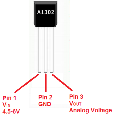
Pin 1 receives positive DC voltage in order for the IC to work. This, again, is voltage between 4.5-6V. Pin 2 is the ground, so it receives the ground or negative terminal of the DC power supply. Pin 3 is the output of the IC, outputting an analog voltage in porportion to the magnetic field it is exposed to.
The arduino, with suitable code, can then interpret this measured analog voltage and output to us the reading.
This is the datasheet of the A1302 Hall Effector Sensor: A1302 Hall Effect Sensor Datasheet.
A good place to purchase this sensor is at Tayda electronics: Tayda Electronics: A1302 Hall Effect Sensor IC.
Also to do this project we need a USB cable with a Type A connector on one end
and a Type B connector
on the other end. This is so that we can hook our arduino to a computer and send it code
that it can run to display
to us the magnetic field reading.
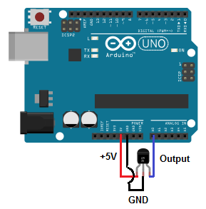
Hall Effect Sensor Circuit
The hall effect sensor circuit we will build is shown below:
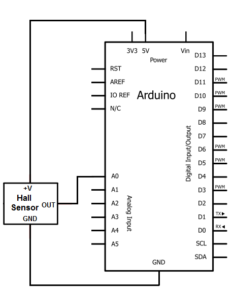
This translates into the circuit schematic:
Now that we have this circuit setup, we now connect the USB cable from the arduino to the computer.
The type B side of the connector goes into the arduino and the type A side into the
USB port of the computer.
Now the computer is connected to the arduino. We can now write code in the processing software to give instructions to the
arduino.
Code for Hall Effect Sensor Circuit
int outputpin= 0;
void setup()
{
Serial.begin(9600);
}
void loop()
{
int rawvalue= analogRead(outputpin);
Serial.println(rawvalue);
delay(5000);
}
This code first defines the pin connections with the first block of code. The second block sets the baud rate at 9600. T he third block of code is the main loop. This simply reads the analog voltage from the output pin of the A1302 sensor. No conversions or computations are done. The raw value is simply read and displayed.
The delay of 5000ms takes measurements every 5 seconds. Since 1000ms is 1 second, 5,000ms= 5 seconds.
This device isn't very sensitive, but if you place a magnet in the vicinity of the hall sensor, you should see a change in reading of the displayed value.
And this is how a hall effect sensor circuit can be built and run.
Related Resources
How to Build a Laser Diode Circuit
How to Build a Relay Driver Circuit
How to Build an Overvoltage Protection Circuit
How to Build a Transient Voltage Suppressor (TVS) Circuit
How to Build a Touch Sensor Circuit
How to Build an Accelerometer Circuit
How to Build a Motion Detector Circuit
How to Build a Vibration Detector Circuit