
How to Build an N-Channel JFET Switch Circuit
In this project, we will go over how to connect an N-Channel JFET to a circuit for it to function as an electronic switch to power on a load.
A JFET is a transistor which is normally on. This means that the JFET will conduct current across from the drain to the source without any voltage input into the gate terminal. JFETs don't need any biasing voltage at the base to turn on. It will conduct across without gate voltage. To turn off an N-Channel JFET, this is when we need to apply voltage- we apply sufficient negative voltage to the gate of the transistor to turn the JFET. This is why JFETs are referred to as being normally on.
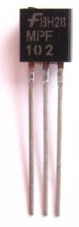
The type of JFET we will use specifically in this circuit is a MPF102. This is a pretty popular N-Channel JFET.
The pinout for the MPF102 is shown below:
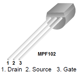
If you deal with BJTs often, it's easy to get into the habit of thinking that the middle pin is the gate, like for a BJT, the middle pin is normally the base, but many times for FETs, this is not the case. The gate can be in the middle or be the 3rd pin, so it's always best to check the datasheet for the pinouts of all JFETs. Otherwise, the circuit will be wired wrong and it won't work.
So that you know which pin, we can go over all components needed for us to build this circuit.
Components Needed for JFET Switch Circuit
- MPF102 JFET
- LED
- 270Ω resistor
- DC Power Supply or 4 'AA' batteries
The MPF102 can be obtained from a number of different electronics online retailers, such as Tayda Electronics.
The datasheet for the MPF102 can be found at the following link: MPF102 N Channel JFET Datasheet.
In this circuit, we power on an LED. We use a 270Ω resistor to act as a current-limiting resistor to the LED.
You can really use any other output device you want such as a buzzer. It doesn't have to be an LED.
N-Channel JFET Switch Circuit Schematic
The schematic diagram of the N-Channel JFET Switch Circuit we will build is shown below.

This circuit is very basic in setup and in operation.
When there is sufficient voltage supplied to the LED and no voltage at the gate terminal, the JFET is fully operational and conducts across from drain to source, turning on and lighting the LED.
To stop current flow, all that is needed is sufficient negative voltage supplied to the gate terminal, about 3-4V. With 3 to 4 volts of negative voltage, the JFET will no longer conduct from drain to source and the LED will turn off.
If using batteries, 2 'AA' batteries (3V) should be enough to turn off the JFET. However, 3 'AA' will give 4.5V which will definitely shut off the JFET, impeding all current flow. So you have the choice of using 2 or 3 batteries at the gate terminal to stop current flow.
And this is how an N-Channel JFET works.
To see how this circuit works in real life, see the video below.
Related Resources
How to Connect a Transistor as a Switch in a Circuit
How to Connect a (NPN) Transistor in a Circuit
Types of Transistors
Bipolar Junction Transistors (BJTs)
Junction Field Effect Transistors (JFETs)
Metal Oxide Semiconductor Field Effect Transistors (MOSFETs)
Unijunction Transistors (UJTs)
What is Transistor Biasing?
How to Test a Transistor