
A NAND Gate Can Be an Active Low or an Active High Device
A NAND gate is a very versatile chip.
A NAND gate can be made to turn on for active low input or active high input, depending on how it is configured.
This means that a NAND gate can turn on a load on its output when fed 0V (this is when it's active low) or when fed a HIGH voltage such as 3-5V (this is when it's active HIGH).
This is significant because it makes NAND gates able to coexist with all types of devices, active low or active high devices.
Therefore, it can really be used
with all types of electronic devices.
NAND Gate as an Active Low Device
NAND gates are naturally active low devices. This means that a LOW signal (0V) turns the output on.
According to NAND logic, if any of the inputs are a logic LOW (0V), then the output will be HIGH (meaning on).
If both inputs are logic HIGH (1), then the output will be LOW (meaning off). Therefore, you can see why it's naturally an active low device
if a single gate is used as it is meant to be as a NAND gate.
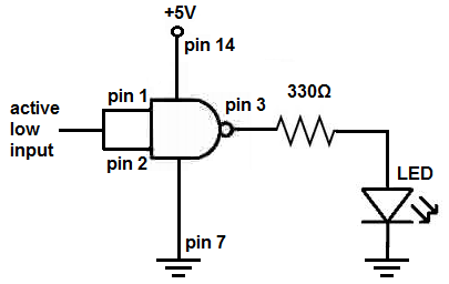
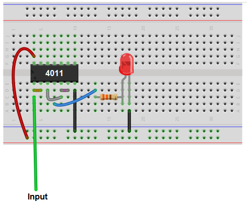
A NAND gate circuit that turns on with active low input is shown below. This, again, is a circuit that will turn on with a 0V
signal.
Below is the breadboard schematic of the above circuit.
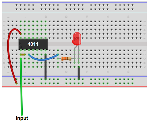
Being that a NAND gate is naturally an active low device, due to NAND logic, we just tie both inputs together. Since 2 0s outputs a logic 1, an logic 0 fed into the input
will yield a logic 1, and the LED will be turned on.
NAND Gate as an Active High Device
A NAND gate, through some clever but still easy circuit wiring, can be made to function as active high device. This means that a HIGH voltage (such as 3-5V) input into the gate turns the output on.
A NAND gate can be converted into an active HIGH device by converting it into an AND gate.
As an AND gate, it will only turn on if both inputs are active HIGH.
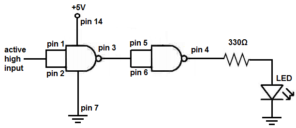
The circuit in which a NAND gate turns on with active high input is shown below.
Below is the breadboard schematic of the above circuit.
This is really a NAND gate converted into an AND gate with the 2 inputs into the first gate tied together.
If the input is a HIGH voltage signal, the load, which is an LED in this circuit, will turn on. If the input is LOW (0V or less than 1/2 of the power supply to the 4011 chip), then
the load, the LED, will be off.
Again, the fact that a NAND gate can be made to turn on either for LOW or HIGH input makes it a truly versatile device that can work with any type of digital or even analog device.
By having the NAND gate naturally be a NAND gate, it can be triggered on by a LOW input and power on a load. By having the NAND gate turned into an AND gate, it can be triggered by a HIGH input
and power on a load. Thus, it is very dynamic and a very useful chip for all types of circuits.
Related Resources
How to Build a Light Detector Circuit with a NAND Gate Chip
How to Build a Night Light Circuit with a NAND Gate Chip
How to Build a NAND Gate Logic Circuit Using a 4011 Chip