
How to Build a NAND Gate Logic Circuit Using a 4011 Chip
In this project, we will build a simple NAND gate circuit using a 4011 quad NAND gate chip.
This circuit is as basic as it gets for a NAND gate circuit and it demonstrates all the possible input values that a NAND gate chip can receive and output.
We will use a 4011 chip as our NAND gate IC.
The 4011 chip is a quad NAND gate IC. This means it is made up of 4 completely independent NAND gates, so we can use up to 4 NAND gates if we want.
However, in this circuit, we will just use one NAND gate, to make the circuit as simple as possible. To the output of the NAND gate we use, we will connect a single LED, just so that we can see visually when the NAND gate turns an output on and off.
For this circuit, we will connect pushbuttons to the 2 inputs of the NAND gate. This way, we can see what combinations of inputs
will make the NAND gate be off and what inputs make it turn on. The pushbuttons, unpressed, will normally be held at a HIGH value of
VCC, giving both inputs a HIGH logic level. When we press down on a pushbutton, it changes to a logic level of LOW. Thus, we can
test out all logic levels.
Components Needed
- 4011 Quad NAND Gate Chip
- 2 10KΩ Resistor
- LED
- 330Ω Resistor
The 4011 quad NAND gate chip can be obtained very cheaply from a number of online retailers for just a few cents. One place it can be obtained from is Tayda Electronics at the following link: Tayda Electronics- 4011 Quad 2-Input NAND Gate IC. However, it is a very popular chip and many electronics parts suppliers have them.
The pinout of the 4011 is shown below, so that you can see how to connect it in the circuit.
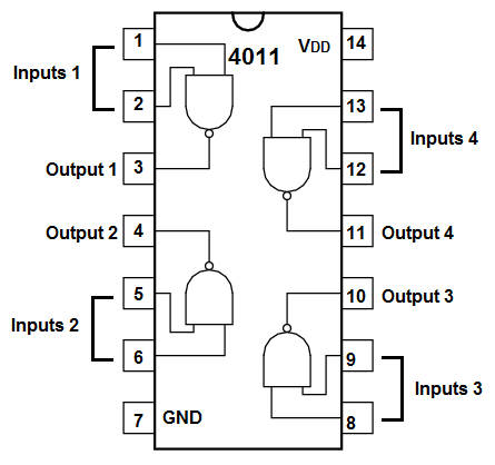
Each NAND gate has input pins and 1 output pin.
The following chart shows NAND gate logic, which shows what output a NAND gate chip will produce for a set of given inputs.
| NAND Gate Logic | ||
| Inputs | Output | |
| 0 | 0 | 1 |
| 0 | 1 | 1 |
| 1 | 0 | 1 |
| 1 | 1 | 0 |
This means that if one of the inputs are a 0, the NAND gate will output a logic HIGH at its output, which means the output will be drawn up to VCC and the load will be powered. If both inputs feeding into the NAND gate are a 1, only then will the NAND gate output a logic LOW at its output, which means the output will be drawn down to GND, and the load will not be powered.
In our circuit, we will use both of these cases.
The other components we need are the LED and the 330Ω resistor in series to limit current to the LED so that it
doesn't burn out.
NAND Gate Logic Circuit Using a 4011
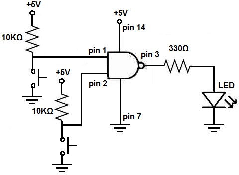
The schematic diagram of the NAND gate circuit using a 4011 is shown below.
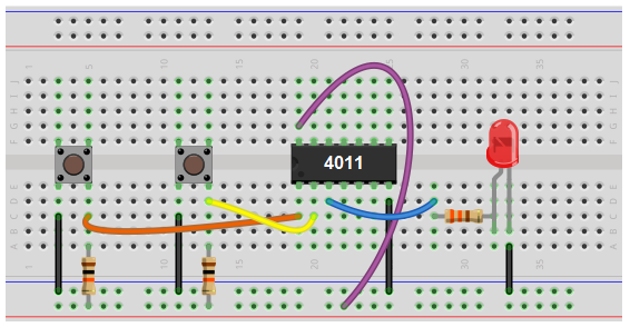
Below is the breadboard schematic version of the above circuit so that you can see the exact wiring of the circuit to the 4011 chip.
First and foremost, we must give power to the 4011 NAND gate chip. We will feed it 5V of power, so we give +5V to pin 14 and we connect pin 7 to GND. This establishes power to the chip.
To each of the pushbuttons we connect a 10KΩ resistor. These resistors function as pull-up resistors. They pull-up the pushbutton to VCC, a logic level of 1, so that the pushbuttons normally have a well-defined logic HIGH (or 1) status. The resistors also keep Vcc from directly shorting to ground when the pushbutton is pushed down. Thus, the pushbuttons, when left alone, unpressed, will normally have a logic value of 1. Thus, when both are unpressed, 2 logic HIGH (or 1) values are input into the NAND gate, which means the NAND will produce a LOW (or 0) output. Remember, that two logic HIGHs will produce an output of logic LOW for a NAND gate. Thus, the NAND gate will not power on the load, so the LED will be off when neither of the pushbuttons are pressed down.
When a pushbutton is pressed down, the pushbutton now makes contact across to ground. The corresponding input pin will now be grounded and its logic level will change to a logic LOW (now that it makes contact down to ground). When either one or both of the pushbuttons are pressed, the NAND gate will output a logic HIGH (or 1), and the load connected to output will be powered on. So the LED will turn on in this case.
And these situations comprise all the situations that can arise for a 2-input NAND gate.
Related Resources
How to Build a Light Detector Circuit with a NAND Gate Chip
How to Build a Night Light Circuit with a NAND Gate Chip
How to Build a Touch Sensor with a NAND Gate Chip