
How to Build an Object-detecting Robot Car
In this circuit, we will build a very simple object-detecting robot car that moves forward when turned on and stops when it encounters an object.
This would be basically used if you want a robot car to keep going forward until it encounters an object, in which case it stops.
When power is on, the motors simply move the car forward. When it encounters an object such as a wall in the room, the robot car will stop (the motors will stop moving). It won't move again after that.
Again, we make it so that it's a very basic first object-detecting robot car.
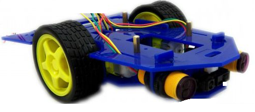
So let's show first how to build this basic object-detecting robot car.
So this article does not go into the mechanics of this circuit, meaning we don't show how to build the frame that the motors rest on, what type of frame you would use, how you would connect the motors mechanically. That you can decide on your own.
We simply just go over the electrical schematic of the circuit and
you can come up with your own mechanical design.
Components Needed
- 2 DC motors
- Infrared proximity sensor switch
- 2N3904 NPN transistor
- 1N4001 Diode
- 2 wheels (to attach to motors)
So depending on your mechanism, this circuit needs at least 2 motors. If you place the motors in the center of the frame, 2 motors can suffice. The design should be mechanically stable.
These 2 motors will be connected together through an axle, just like with a car. This is so that the 2 motors are connected together and move together.
Since motors typically require quite a bit of current to operate, we use a transistor to amplify current so that it can provide enough current to power both motors.
Of course, wheels must be attached to the shafts of the DC motors to work.
Whatever voltage rated motor you are using, you use that voltage to power on the motor. For example, in the circuit schematic shown below, we use 6V motors. But if you are using 9V motors, then you would have to use 9V of power.
We simply only need one infrared proximity sensor switch. This forms the "eyes" of the circuit. The infrared proximity sensor switch, when it detects no object, outputs a high voltage. When it detects an object in front of it, it outputs a low voltage. We simply can connect this output voltage directly to the base of the transistor. Since we want the motor to run (the car to go forward) when no object is detected, this the perfect setup. The robot car will go forward when there is no object detection. When an object is detected, the low voltage output by the infrared proximity sensor switch is not enough to turn on the base of the transistor and, thus, the motors are off.
The infrared proximity sensor switch should be placed right in the front of the car and be centered in the middle.
Below is the circuit schematic.
Object-detecting Robot Car Circuit
The object-detecting robot car we will build with a 4011 NAND gate chip is shown below.
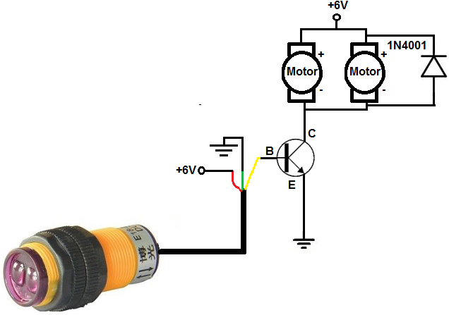
So the first thing that is need is power. The infrared proximity sensor needs power. And the transistor needs power. We give them both the same power, 6V, to keep the circuit basic. As long as the motors are 6V motors, it will work. If the motors are 9V or 12V motors, then you would need that amount of voltage for them.
So the infrared proximity sensor outputs a HIGH voltage when no object is detected. This gives sufficient voltage to the base of the transistor, so that the transistor turns on. This, in turn, makes the motors conected to the collector of the transistor turn on. So when no object is detected, the motors are on, meaning the robot car is moving forward.
When an object is detected, the infrared proximity sensor switch outputs a LOW voltage, near 0V. This is not enough power to turn on the transistor. Thus, the motors are off and the robot car stops. This is when the robot car encounters an object such as a wall.
So this robot car works by moving forward when nothing is in front of it and stopping when it encounters an object in front of it.
This is all it does in this very basic model and setup.
Related Resources
How to Build a Touch On-Off Circuit with a 4011 NAND Gate Chip
How to Build a Touch On-Off Circuit with a 4001 NOR Gate Chip
How to Build a Touch On-Off Circuit with a 7414 Inverter Gate Chip