
How to Build a P-Channel JFET Switch Circuit
In this project, we will go over how to connect a P-Channel JFET to a circuit for it to function as an electronic switch to power on a load.
A JFET is a transistor which is normally on. This means that the JFET will conduct current across the source-drain region without any voltage input into the gate terminal. JFETs don't need any biasing voltage at the gate terminal to turn on. It will conduct across without gate voltage. To turn off a P-Channel JFET, this is when we need to apply voltage- we apply sufficient positive voltage to the gate terminal to turn the JFET off. This is why JFETs are referred to as being normally on.
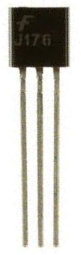
The type of JFET we will use specifically in this circuit is a J176. This is a pretty popular P-Channel JFET.
The pinout for the J176 is shown below:
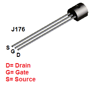
If you look at the transistor from a back view, the left most pin is the drain, the middle pin is the gate, and the rightmost pin is the source.
So that you know which pin is which, we can go over all components needed for us to build this circuit.
Components Needed
- J176 JFET
- 6V Buzzer
- DC Power Supply or 6 'AA' batteries
The J176 can be obtained from a number of different electronics online retailers such as ebay.
The buzzer chosen can really be any type of buzzer. Just make sure that the voltage supplied to the buzzer at the source terminal meets the buzzer's power requirements.
P-Channel JFET Switch Circuit Schematic
The schematic diagram of the P-Channel JFET Switch Circuit we will build is shown below.
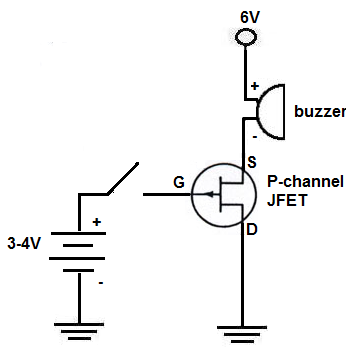
This circuit is very basic in setup and in operation.
When there is sufficient voltage supplied to the buzzer and no voltage at the gate terminal, the JFET is fully operational and conducts across from source to drain, turning on and sounding the buzzer.
To stop current flow, all that is needed is sufficient positive voltage supplied to the gate terminal, about 2-4V. With 2 to 4 volts of positive voltage to the gate, the JFET will no longer conduct current from source to drain and the buzzer will turn off.
If using batteries, 2 'AA' batteries (3V) should be enough to turn off the JFET. However, 3 'AA' will give 4.5V which will definitely shut off the JFET, impeding all current flow. So you have the choice of using 2 or 3 batteries at the gate terminal to stop current flow.
And this is how a P-Channel JFET works.
To see how this circuit works in real life, see the video below.
Related Resources
How to Connect a Transistor as a Switch in a Circuit
How to Connect a (NPN) Transistor in a Circuit
Types of Transistors
Bipolar Junction Transistors (BJTs)
Junction Field Effect Transistors (JFETs)
Metal Oxide Semiconductor Field Effect Transistors (MOSFETs)
Unijunction Transistors (UJTs)
What is Transistor Biasing?
How to Test a Transistor