
How to Build an P-Channel MOSFET Switch Circuit
In this project, we will go over how to connect an P-Channel MOSFET to a circuit for it to function as an electronic switch.
The type of P-Channel MOSFET we will use is the enhancement-type MOSFET, the most commonly used type of MOSFET.
MOSFETs, like BJTs, can function as electronic switches. Although unlike BJTs, MOSFETs are turned on, not by current, but by voltage.
MOSFETs are voltage-controlled devices. This means that a voltage applied to the gate controls whether the transistor switches on or off. When a P-channel (enhancement-type) MOSFET has no voltage at its gate, it is OFF and no current conducts across from source to drain; thus, the load connected to the MOSFET will not turn on. When there is sufficient voltage at the gate (about -3V), the MOSFET is on and current conducts across from the source to the drain to power on the load.
Know the distinction between a voltage-controlled device and a current-controlled device. MOSFETs are voltage-controlled.
This means that only voltage has
to be applied to the gate for it turn on. It does not need current. Therefore, when we are wiring up the P-channel MOSFET, we simply connect the voltage
source to the
gate terminal. No resistor is necessary, as would be the case for a bipolar junction transistor, which is current-controlled. We simply connect a negative
voltage to the
gate terminal without an external resistor. Therefore, with a MOSFET, biasing the circuit is actually a little simpler than with BJTs.
Components Needed
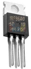
- IRF9640 MOSFET
- DC Motor or Buzzer
- 6 'AA' batteries or Dual DC Power Supply
In our circuit, we are going to use the IRF9640 P-channel MOSFET.
The IRF9640 is an enhancement-type MOSFET, meaning as more negative voltage is fed to the gate, the current from the drain to the source increases. This is in contrast to depletion-type MOSFETs, in which increasing negative voltage to the base blocks the flow of current from the drain to the source, while placing no voltage at the gate makes the MOSFET fully on.
Know that an P-channel MOSFET, like all MOSFETS, have 3 pins, the drain, the gate, and the source.
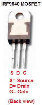
If you look at the back view of the transistor, as shown above, the leftmost pin will be the source, the middle pin is the drain, and the rightmost pin is the gate. This is a very different pinout than the N-Channel MOSFET, so make sure you observe this for your connection setup.
The gate terminal is where we connect about -3 volts to power on the transistor (to make it turn on).
The source terminal is where we connect our output device that we want to power. And when connecting our load, if the device is polarity-sensitive, such as LEDs and buzzers are, the anode terminal must be connected to the positive voltage, while the cathode end connects to the source terminal. Or else, it won't work, because current in an P-channel MOSFET flows from source to drain. If we hooked up an LED, reverse biased, so that its anode was connected to the drain terminal and its cathode was connected to the positive voltage source, it would not work.
The last terminal, the drain, simply connects to ground. Since current flows source to drain, the drain must be grounded to create a return path.
The IRF9640 datasheet is can be be viewed here:
IRF9640 MOSFET datasheet.
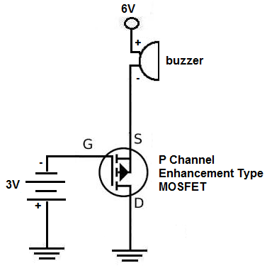
P-Channel MOSFET Circuit Schematic
The schematic for the P-Channel MOSFET circuit we will build is shown below.
So, this is the setup for pretty much any P-Channel MOSFET Circuit.
Negative voltage is fed into the gate terminal. For an IRF9640 MOSFET, -3V at the gate is more than sufficient to switch the MOSFET on so that it conducts across from the source to the drain. Now that we have hooked up sufficient voltage to the gate to turn on the transistor, then we must supply voltage to our load on the source terminal of the transistor. Remember, one voltage is to turn on the transistor and the other voltage is to power the load once the transistor has been turned on.
The amount of voltage that needs to be connected to the load depends entirely on how much voltage the load needs to be powered on. If you are using a 6V DC motor or buzzer, then you connect 6V to the source terminal. If you are powering a 12V motor or buzzer, then you connect 12V.
Since the buzzer we are using in this circuit requires 6V, 6V is connected to the source terminal.
And this is how an P-Channel MOSFET is set up and works.
To see how this circuit works in real life, see the video below.
Related Resources
P Channel MOSFET Basics
How to Connect a Transistor as a Switch in a Circuit
How to Connect a (NPN) Transistor in a Circuit
Types of Transistors
Bipolar Junction Transistors (BJTs)
Junction Field Effect Transistors (JFETs)
Metal Oxide Semiconductor Field Effect Transistors (MOSFETs)
Unijunction Transistors (UJTs)
What is Transistor Biasing?
How to Test a Transistor