
PIC Analog to digital conversion (ADC)
This article will go over how analog to digital conversion is achieved with a PIC microcontroller.
An analog to digital converter takes an the output of an analog device and converts the analog output into a digital value. This is because microchips can only process digital values. So analog values must be converted into digital values in order to be able to be interpreted by a microchip.
Once we have the digital equivalent of the analog signal, we have the measurement of the analog signal that the microchip can understand.
Analog to digital converters (ADCs) allow for analog input or output to a microcontroller. Otherwise, analog devices couldn't work and coexist with them.
ADCs are in use whenever we are dealing with analog values, whether input or output. Again, it's the only way microchips can
understand analog signals.
Analog Pins
In order to do ADC conversions, a pin on the microcontroller must be capable of being an analog pin. The pins which are analog on a PIC microcontroller are labeled ANx, where X is a number. PIC microcontrollers vary greater in the number of analog pins available. It may have only 5 (AN0 to AN4). It may have 8 (AN0 to AN7). The PIC18F1220 has 7 analog pins (AN0 to AN6).
Again, the ANx pins are the only pins which can be used with analog signals. Therefore, if you have an analog device, whether input or output, it must be connected to one of these pins.
Check the datasheet of the PIC microcontroller you are using to determine which pins can be used as analog pins. Again, you can
tell which pins because they will be labeled ANx.
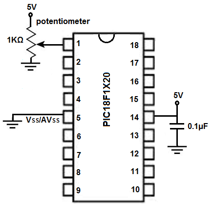
Example ADC Circuit
As an example circuit, we have a potentiometer connected to analog pin, AN0.
Through this setup, we can read the analog value from the potentiometer circuit.
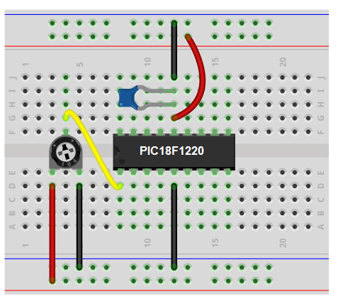
Below is the breadboard schematic of the above circuit.
PIC Programming- ADC Conversion
Before we do an ADC conversion, we must first specify and declare a pin to be analog. We do this through the ADCON1 register. This register references pins AN0 to AN7. By writing a 1 a bit in the register, it makes a pin a digital pin. By writing a 0 to the bit in the register, it makes the pin an analog pin. So if we're using pin AN0 as an analog input pin, ADCON1= 0b01111110;
Our golden sample code for ADC conversion is shown below.
#include <p18f1220.h>
#pragma config WDT=OFF, OSC=INTIO2, PWRT=ON, LVP=OFF, MCLRE=OFF
#include <delays.h>
int analog_reading;
void main(void)
{
//SET UP
ADCON1= 0b01111110;
TRISA= 0b11111111;
ADCON0bits.ADON=1;
ADCON2= 0b10000000;
while (1)
{
ADCON0bits.GO_DONE=1; //do A/D measurement
while(ADCON0bits.GO_DONE==1);
analog_reading= ADRESL + (ADRESH *256);
}
}
ADCON1 allows us to select which bits are analog and which are digital.
TRISA sets the PORTA as inputs.
ADCON0bits.ADON=1 turns on the ADC.
ADCON2 sets an acquisition time of the ADC conversion, basically how fast it will take to convert an analog value to a digital value. Unless you have time crucial applications, you can keep the value above as a default.
We then run an infinite while loop, which runs over and over and over again, updating the ADC value each time it loops.
ADCON0bits.GO_DONE=1 starts the ADC conversion process.
While(ADCON0bits.GO_DONE==1); waits until the ADC process is done.
Then finally, once done, the value of the ADC process is stored in the ADRESL and ADRESH registers. The 2 registers added up gives the equivalent analog reading.
This circuit simply reads the analog value from the potentiometer. It doesn't do anything interesting but simply demonstrated how ADC conversion is done at its simplest degree.
After we take the ADC measurement and have the analog value, we can take any action based on the value. For example, if the analog value is greater than 700, we can turn on an LED. Or if it's below 700, we can turn on a fan. Or if it's between 200 and 500, we can turn on a motor. Or we can write the analog reading obtained from the potentiometer to the analog output so that the analog input controls the analog output.
This circuit serves as the blueprint for us doing anything we want with analog signals.
Related Resources
How to Program a PIC Microcontroller