How to Program a PIC Microcontroller Chip
We will go over how to program a PIC microcontroller chip.
By programming a PIC microcontroller, we mean we transfer the program which we compiled into the flash memory of the PIC chip, so that it is written into the memory of the chip, so that it can then run the program.
So the steps are, first we write the program we want the chip to run, then we compile the program so that it is in machine code for the chip to understand, then we transfer the compiled version to the flash memory of the chip, so that the program is stored in the chip. Once stored on the chip, the program can then be run.
So if the program is meant to blink an LED, once the program is transferred, the LED should blink.
Components Needed
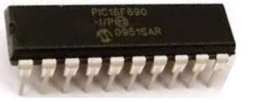
In order to program a PIC microcontroller, we need a PIC programmer.
This is a specialized circuit that can write to the flash memory of a PIC chip. This way, the chip can store the program to eventually run it.
The official programmer for Microchip PIC chips is the PICkit2 and Pickit 3.
The PICKit2, though, is an older model and cannot program the newest and latest microchips. Therefore,
it is much recommended to use the PICkit3.
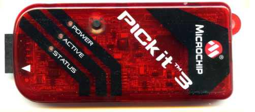
The PICkit3 programmer can program any PIC chips.
It can be obtained moderately priced from the microchip site for about $45 at the following link: Microchip PICkit3. At $45, it is an investment. But if you're going to be programming PIC chips, it's pretty much a most. It's the only official programmer from microchip that gets large-scale support from them. Therefore, it's worth it.
The PICKit3 ICSP (in-circuit serial programmer) has 6 connectors. Pin 1 is labeled with an arrow,
indicating it's pin 1.
The pinout for the ICSP connector is shown below.
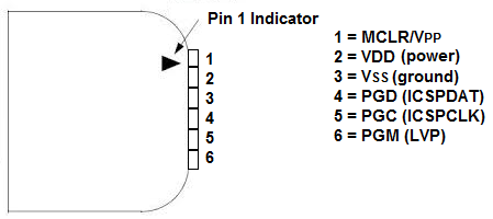
The
VDD supplies positive voltage to the programmer.
VSS gets connected to ground.
PGD is the data line of the programmer. It transfers all the data of the program.
PGC is the clock line. This allows synchronous communication between the programmer and the microchip being programmed.
PGM is an optional line. It allows the programmer to run on low voltage. We won't use in our circuit.
These explain all the pins and their associated functions.
Connecting the PICKit3 ICSP to a PIC chip
Connecting the PicKit3 ICSP to a PIC chip is as easy as can be.
All of the connectors have a direct equal on the PIC chip and directly match up.
The circuit schematic below shows the connection of the programmer ICSP to a target PIC chip.
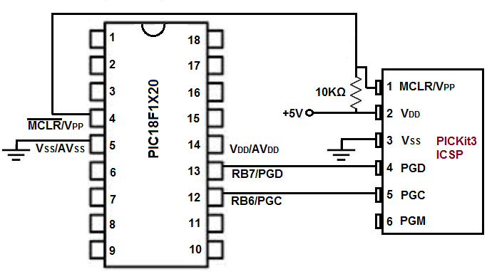
With the PICKit3 connected to a computer via USB, data (such as a compiled program) can travel from the host computer to the flash memory of a PIC microchip.
And this is how a PIC microcontroller can be programmed.
Related Resources
How to Build a Light Detector Circuit with a NAND Gate Chip
How to Build a Night Light Circuit with a NAND Gate Chip
How to Build a NAND Gate Circuit Using a 4011 Chip