PIC Blinking LED Circuit
In this circuit, we will blink an LED on and off at 1-second intervals with a PIC microcontroller, specifically the PIC18F1220.
But you can really substitute this chip for another PIC. You would just have to get the datasheet to see the pinout setup for that particular microcontroller.
This circuit is like one of the beginning basic circuits, but it demonstrates a lot. It demonstrates how to turn on and off digital output. And it demonstrates how to use delays, so that we can have a device such as an LED off and on for a period of time.
Programming PICs or any microcontroller chips directly is an amazing thing, for a number of reasons. See
Why programming a PIC or AVR
directly is an upgrade to programming an arduino.
Components Needed
- PIC18F1220 Chip
- 0.1μF ceramic capacitor
- 470Ω resistor
- LED
The PIC18F1220 is an 18-pin microcontroller. It can be obtained for a few dollars at various places online (under $3).
The pinout for the PIC18F1220 is shown below.
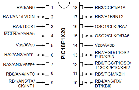
The PIC18F1220 has 16 I/O pins. This means that 16 of the pins can either serve as inputs or outputs. There are 2 major ports, Port A and Port B, which are each comprised of 8 I/O pins. For Port A, these are labeled RA0 to RA7. For Port B, these are labeled RB0 to RB7.
The other 2 pins are the power pins, VDD and VSS. VDD is the pin which receives the positive voltage. VSS is the pin which gets connected to ground. These pins establish power to the PIC chip. Usually a ceramic capacitor is placed on the positive voltage rail to act as a reservoir capacitor.
Apart from the microchip, an LED along with its current-limiting resistor is needed, which will serve as an output to the circuit.
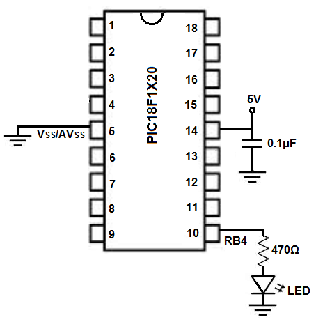
PIC18F1220 Blinking LED Circuit Schematic
The circuit schematic for the blinking LED we will build with a PIC18F1220 chip is shown below.
The breadboard schematic of the above circuit is shown below.

We establish power to the chip by connecting pin 14 to 5V through a capacitor that connects on the other end to ground. We connect pin 5 to ground.
We connect the LED to Port B pin 4, which is pin 10 on the PIC18F1220 chip. The 470Ω resistor serves as a current-limiting resistor to prevent the LED from burning out.
The hardware setup is extremely simple. All we need now is the code.
Code
#include <p18f1220.h>
#pragma config WDT=OFF, OSC=INTIO2,PWRT=ON, LVP=OFF, MCLRE=OFF
#include <delays.h>
void main (void){
ADCON1= 0x7F;
TRISB= 0b00000000;
PORTB= 0b00000000;
while(1){
PORTBbits.RB4=1;
Delay100TCYx(78);
PORTBbits.RB4=0;
Delay100TCYx(78);
}
}
The first block includes all the header files we will need as well as initialize a number of key values.
The second block of code is the main method. This initializes the I/O pins so that they are all digital pins and so that Port B are all outputs and are initially off.
The last block is the while() loop. This is the loop that executes over and over again, infinitely, in an infinite loop. The LED turns on since we write a 1 to RB4. We then call a delay function that keeps the LED on for 1 second. We then turn the LED off by writing a 0 to RB4. We then call the delay function again to keep the LED off for 1 second.
And this behavior initializes blinking of the LED.
Related Resources
How to Program a PIC Microcontroller