PIC Night Light Circuit
In this circuit, we will show how to build a night light circuit using a PIC microcontroller.
A night light circuit is a circuit in which a light will turn on when the circuit senses darkness in the ambient environment, such as will happen during the onset of night time.
Night light circuits are very popular and can be found in many different stores selling household items. Automatic night lights are especially common in backyards or at the side of houses, where they will turn on automatically at the onset of night.
Using a PIC microcontroller, we can easily build a night light circuit.
Using a photoresistor, we can sense the ambient lighting conditions of an environment.
We place the photoresistor in a voltage divider circuit with a resistor. Based on the ambient lighting, the photoresistor will have output different resistance values. This resistance value will directly determine the voltage that falls across each component in the voltage divider circuit.
Being that a PIC microcontroller can be configured to read analog input, it can read the voltage value from the resistor in the
voltage divider circuit and know whether it is dark or bright in the ambient environment. If dark enough, the LED will turn on.
Components Needed
- PIC18F1220 Chip
- 0.1μF ceramic capacitor
- GL5537 photoresistor
- 33KΩ resistor
- 470Ω resistor
- LED
The PIC18F1220 is an 18-pin microcontroller. It can be obtained for a few dollars at various online retailers.
The pinout for the PIC18F1220 is shown below.
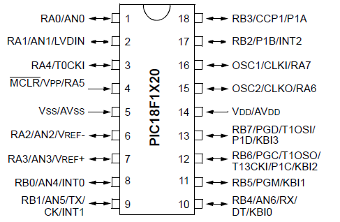
The PIC18F1220 has 16 I/O pins. This means that 16 of the pins can either serve as inputs or outputs. There are 2 major ports, Port A and Port B, which are each comprised of 8 I/O pins. For Port A, these are labeled RA0 to RA7. For Port B, these are labeled RB0 to RB7.
The other 2 pins are the power pins, VDD and VSS. VDD is the pin which receives the positive voltage. VSS is the pin which gets connected to ground. These pins establish power to the PIC chip. Usually a ceramic capacitor is placed on the positive voltage rail to act as a reservoir capacitor.
The photoresistor that we will use is a GL5537 photoresistor. Basically, its light resistance can go as low as 6KΩ and its dark resistance will be greater than 130KΩ. Either way, it's a huge resistance swing from darkness and bright conditions. This huge swing allows us to know whether there is brightness or darkness in the ambient environment.
Besides the photoresistor, we will need an LED along with a 470Ω resistor to limit current to the LED so that it doesn't burn out.
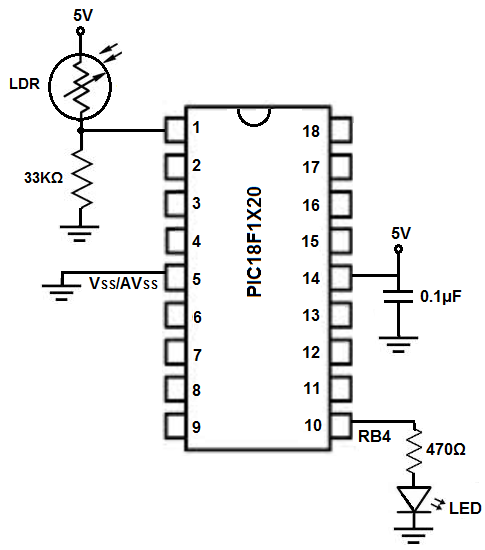
PIC18F1220 Night Light Circuit Schematic
The circuit schematic for the night light circuit we will build with a PIC18F1220 chip is shown below.
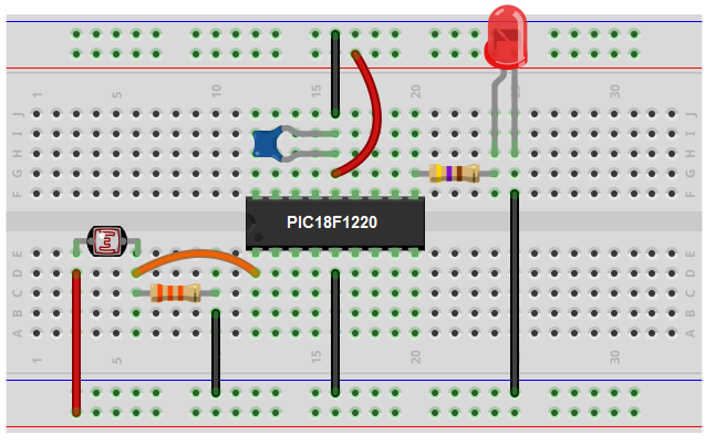
The breadboard schematic of the above circuit is shown below.
We establish power to the chip by connecting pin 14 to 5V through a capacitor that connects on the other end to ground. We connect pin 5 to ground.
Next, we create a voltage divider circuit consisting of a photoresistor and a 33KΩ fixed resistor. When exposed to total darkness, the photoresistor will have a resistance in excess of 130KΩ, much greater than the 33KΩ resistor. Thus, in a voltage divider circuit, the majority of the voltage will fall across the photoresistor in dark conditions and very little voltage will fall across the fixed resistor. In bright conditions, the photoresistor's resistance drops dramatically. It may go to 20KΩ in room lighting and may even go as low as 6KΩ in very bright light. Thus, in a voltage divider, most of the voltage will fall across the fixed resistor and very little across the photoresistor.
We connect this voltage divider circuit to an analog input of the microcontroller. In our case, will connect it to analog pin 0, AN0.
The PIC18F1220 has 7 analog pins, AN0 to AN6. These are pins RA0, RA1, RA2, RA3, RBO, RB1, and RB4, which are pins 1, 2, 6, 7, 8, 9 and 10, respectively. Technically, we could connect the voltage divider circuit to any of these pins. We would just need to set the pins to analog input in the code, which we will show how to do below.
In this circuit, we will set the LED pin, which is pin RB4, as a digital output. This is because we want it to either be on or off. It will be off initially.
So the voltage divider circuit connects to AN0 (RA0), which is pin 1, and the LED connects to RB4, which is pin 10.
Code
#include <p18f1220.h>
#pragma config WDT=OFF, OSC=INTIO2, PWRT=ON, LVP=OFF, MCLRE=OFF
#include <delays.h>
int analog_reading;
void main(void)
{
//SET UP
//OSCCON defaults to 31KH.
ADCON1= 0b01111110; //AN0 is analogue
TRISA= 0b11111111; //sets PORTA as all inputs, bit0 is AN0
TRISB= 0b00000000; //sets PORTB as all outputs
PORTB= 0b00000000; //sets all outputs of PORTB off to begin with
ADCON0bits.ADON=1; //turns on A/D
ADCON2= 0b10000000; //right justified, acquisition times are at 0 with 31KHz
while (1)
{
ADCON0bits.GO_DONE=1; //do A/D measurement
while(ADCON0bits.GO_DONE==1);
analog_reading= ADRESL + (ADRESH *256);
if (analog_reading < 270){
PORTBbits.RB4= 1;
}
else{
PORTBbits.RB4=0;
}
}
}
The first block of code is the include files and initializations.
Next we create a variable analog_reading, which will hold read the analog voltage that falls across the fixed resistor in the voltage divider circuit.
the next block of code is the main loop. Here in the first few lines we provide important initializations. We make pin AN0, which is RAO (pin 1) an analog pin, so that the pin can read the analog voltage from the voltage divider circuit. The rest of the pins we make digital pins. We then set PORTA to be all inputs, because the voltage divider circuit serves as an input to the microcontroller. We then set PORTB as all outputs. This is the port that contains RB4, which we will connect our LED to. RB4 is set as a digital output. It turns the LED ON or OFF with no intermediate states.
The next block is our while (1) loop. This creates an infinite loop that the code runs over and over and over again infinitely, unless the program is stopped. The rerunning infinitely is good because the code updates the value from the voltage divider circuit continuously getting new readings. So the circuit will adjust automatically to the lighting conditions read from the photoresistor.
Next specifically in this circuit, the voltage divider is the key. The voltage divider output is the voltage that falls across the fixed resistor. This is the reading that will be held in the analog_reading variable. In dark conditions, the photoresistor has very high resistance, so most of the voltage drops across the photoresistor and very little across the photoresistor. Thus, in dark conditions, the voltage divider circuit will have a very low analog reading. Let's say the resistance across the photoresistor is 130KΩ, then the analog output will be (33KΩ/130KΩ)(1024)= 260. Thus, when in total darkness, the analog reading should be about 260. This is why in our code, we make the if loop so that if the analog reading is below 270, the LED will turn on. Else, it should be off.
So this is how a night light can be built with a PIC microcontroller.
Related Resources
How to Program a PIC Microcontroller