
PIC Potentiometer Circuit
In this circuit, we will show how to connect a potentiometer to a PIC microcontroller.
The potentiometer serves as an analog input to the microcontroller.
Being that a potentiometer can have any value from 0Ω to its rated resistance, it can have any voltage value from 0V up to the full voltage supplied to it. Therefore, with a potentiometer, we can input any voltage from 0V to full voltage on the positive rail. So it's very dynamic. A digital input, on the other hand, can input only 0V or full voltage, with no value in between.
Analog input, then, such as from a potentiometer is more dynamic and can take on many more values.
A potentiometer is a very simple device to connect to a microcontroller.
Components Needed
- PIC18F1220 Chip
- 1KΩ Potentiometer
- 0.1μF ceramic capacitor
The PIC18F1220 is an 18-pin microcontroller. It can be obtained for a few dollars at various online retailers.
The pinout for the PIC18F1220 is shown below.
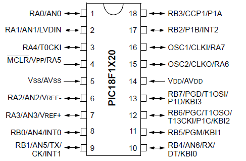
The PIC18F1220 has 16 I/O pins. This means that 16 of the pins can either serve as inputs or outputs. There are 2 major ports, Port A and Port B, which are each comprised of 8 I/O pins. For Port A, these are labeled RA0 to RA7. For Port B, these are labeled RB0 to RB7.
The other 2 pins are the power pins, VDD and VSS. VDD is the pin which receives the positive voltage. VSS is the pin which gets connected to ground. These pins establish power to the PIC chip. Usually a ceramic capacitor is placed on the positive voltage rail to act as a reservoir capacitor.
The potentiometer we will use in this circuit really can be any value. In this circuit, we use a 1KΩ potentiometer, but you can
use any value potentiometer you want. The result will be the same.
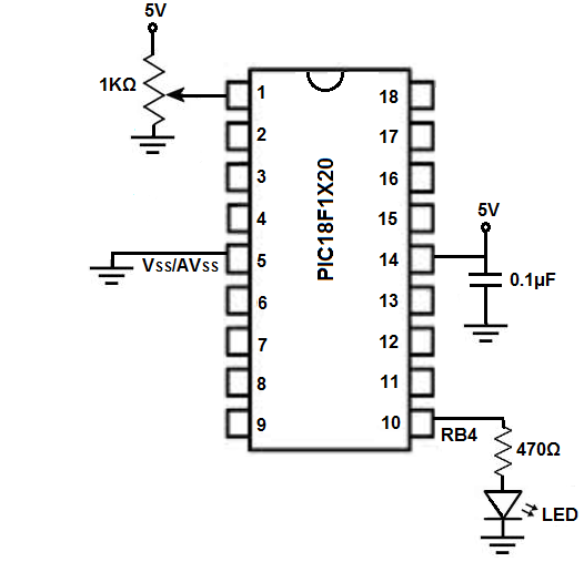
PIC18F1220 Potentiometer Circuit Schematic
The circuit schematic for the potentiometer circuit we will build with a PIC18F1220 chip is shown below.
The breadboard schematic of the above circuit is shown below.
We establish power to the chip by connecting pin 14 to 5V through a capacitor that connects on the other end to ground. We connect pin 5 to ground.
The potentiometer has 3 terminals. There are 2 end terminals and a wiper terminal. One side of the end terminals connects to +5V and the other end connects to ground. The wiper terminal, whose resistance adjusts, connects to analog pin ANO, which is pin 1 of the microcontroller.
The PIC18F1220 has 6 analog pins, AN0 to AN5. These are pins RA0, RA1, RA2, RA3, RBO, RB1, and RB4, which are pins 1, 2, 6, 7, 8, 9 and 10, respectively. Technically, we could connect the potentiometer to any of these pins to allow for analog input from the potentiometer. We would just need to set the pins to analog input in the code, which we will show how to do below.
So the potentiometer connects to AN0 (RA0), while the LED connects to AN6 (RB4).
Code
#include <p18f1220.h>
#pragma config WDT=OFF, OSC=INTIO2, PWRT=ON, LVP=OFF, MCLRE=OFF
#include <delays.h>
int analog_reading;
void main(void)
{
//SET UP
ADCON1= 0b00111110; //AN0 ad AN6 are analogue
TRISA= 0b11111111; //sets PORTA as all inputs, bit0 is AN0
TRISB= 0b00000000; //sets PORTB as all outputs
PORTB= 0b00000000; //sets all outputs of PORTB off to begin with
ADCON0bits.ADON=1; //turns on A/D
ADCON2= 0b10000000; //right justified, acquisition times are at 0 with 31KHz
while (1)
{
ADCON0bits.GO_DONE=1; //do A/D measurement
while(ADCON0bits.GO_DONE==1);
analog_reading= ADRESL + (ADRESH *256);
if (analog_reading > 512){
PORTBbits.RB4= 1;
}
else{
PORTBbits.RB4=0;
}
}
}
The first block of code is the header file. This includes all the external files we'll need along with initialization code for things such as the watchdog timer, oscillator, and so on.
The second block of code initializes a variable, analog_reading, which we will use to store the analog value that the potentiometer reads. Since the PIC18F1220 contains a 10-bit analog-to-digital converter (ADC), it can hold a possible 1024 values, because 210 is 1024. Therefore, the value that we read from the ADC can vary from 0 to 1023. This means the potentiometer can return anywhere from 0 to 1023. This, again, is stored in the analog_reading variable.
In our main loop, we initialize the ADCON1 variable, which allows us to control all 7 of our analog pins. These are pins AN0 to AN6. By writing a 1 to the pin, it will be a digital pin. By writing a 0 to the pin, it will be an analog pin. Since we are using AN0 and AN6, we write a 0 to the bits 0 and 7 of ADCON1, while having the rest be 1s for digital. An analog bit 8 does not exist, so a 0 gets written to it just as a default value. We set PORTA as inputs, since the potentiometer will be connected to RA0 and the potentiometer serves as as input to the microcontroller. We set PORTB as outputs because the LED will be attached to pin RB4 and the LED serves as an output. We initially have the LED off.
The analog_reading is obtained from using 2 registers, ADRESL and ADRESH. Since the ADC is 10 bits, it cannot fit into a single register. This is why we must use 2 registers to hold the entire 10-bit value. The low byte ADRESL counts up to 256 and overflows. The high byte ADRESH is incremented every time ADRESL overflows, i.e., ADRESH is counting how mnay 256s there have been.
In our code, our analog_reading variable reads the value from the potentiometer. This is a simple
script. The ADC value can vary from 0 to 1023, with 512 being just about the halfway point. If the voltage being output
by the potentiometer reaches above half of the supply voltage of 5V, then the LED turns on. This would be 2.5V. If the
voltage is less than this, the LED is off.
Related Resources
How to Program a PIC Microcontroller