
PIC Pushbutton Switch Circuit
In this circuit, we will show how to add a pushbutton switch to a PIC microcontroller so that the pushbutton can control output.
In the circuit we will build, when the pushbutton is pressed down, an LED will light up.
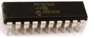
Specifically, we will use the PIC18F1220 microcontroller.
This circuit functions as a fundamental circuit for inputs to a microcontroller.
The pushbutton, in this case, serves as an input to the microcontroller, which then controls the output, which in this case is an LED.
Specifically, in this circuit, the input is a digital input. It can either be ON or OFF, HIGH or LOW, 1 or 0.
Later, in another project, we will go through analog input. But for this circuit, a switch is digital, so we're dealing with digital input.
This is really important because it serves as the foundation for any digital input. A prime example of a digital input which is ubiquitious in electronic devices are switches. Switches can do everything from powering on a device, to turning on a particular feature, etc. Thus, knowing how to interface digital input such as switches with a microcontroller such as a PIC is really the foundation.
And it's very basic. In this project, we will lay all the steps from hardware setup to code needed to obtain and use data from an
input source to control output.
Components Needed
- PIC18F1220 Chip
- Normally Open Pushbutton Switch
- 0.1μF ceramic capacitor
- 470Ω resistor
- LED
The PIC18F1220 is an 18-pin microcontroller. It can be obtained for a few dollars at many online retailers.
The pinout for the PIC18F1220 is shown below.
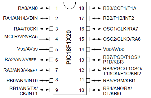
The PIC18F1220 has 16 I/O pins. This means that 16 of the pins can either serve as inputs or outputs. There are 2 major ports, Port A and Port B, which are each comprised of 8 I/O pins. For Port A, these are labeled RA0 to RA7. For Port B, these are labeled RB0 to RB7.
The other 2 pins are the power pins, VDD and VSS. VDD is the pin which receives the positive voltage. VSS is the pin which gets connected to ground. These pins establish power to the PIC chip. Usually a ceramic capacitor is placed on the positive voltage rail to act as a reservoir capacitor.
Apart from the microchip, an LED along with its current-limiting resistor is needed, which will serve as an output to the circuit.
A normally open pushbutton should be used, for the input. This means it normally does not make contact across its leads, unless pushed down. So when
not pushed, it is open (forms an open circuit). And when pushed down, it is closed (forms a closed circuit).
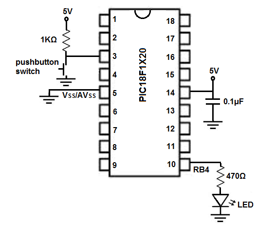
PIC18F1220 Pushbutton Switch Circuit Schematic
The circuit schematic for the blinking LED we will build with a PIC18F1220 chip is shown below.
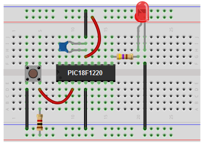
The breadboard schematic of the above circuit is shown below.
We establish power to the chip by connecting pin 14 to 5V through a capacitor that connects on the other end to ground. We connect pin 5 to ground.
We connect the LED to Port B pin 4, which is pin 10 on the PIC18F1220 chip. The 470Ω resistor serves as a current-limiting resistor to prevent the LED from burning out.
We connect the pushbutton to RA4, which is Port A pin 4 of the microcontroller. This is pin 3 of the PIC18F1220. One end of the pushbutton gets connected to ground and the other end gets connected to the 5V positive voltage rail through a 1KΩ resistor. This resistor serves as a pull-up resistor, pulling up the RA4 pin to a HIGH voltage. When pressed down, the switch now make direct contact with ground and the pin drops to a LOW value. The microcontroller can easily read whether there is voltage on the pin (HIGH state) or there is no voltage on the pin (LOW state).
The hardware setup is extremely simple. All we need now is the code.
Code
#include <p18f1220.h>
#pragma config WDT=OFF, OSC=INTIO2,PWRT=ON, LVP=OFF, MCLRE=OFF
#include <delays.h>
void main (void){
ADCON1= 0x7F;
TRISA= 0b11111111;
TRISB= 0b00000000;
PORTB= 0b00000000;
while(1){
if (PORTAbits.RA4==0)
else
PORTBbits.RB4=0;
}
}
The first block includes all the header files we will need as well as initialize a number of key values.
The second block of code is the main method. This initializes the I/O pins so that they are all digital pins and so that Port A are all inputs, while Port B are all outputs and are initially off.
The last block is the while() loop. This is the loop that executes over and over again, infinitely, in an infinite loop. If the pin at RA4 is LOW (near 0V), then the LED will turn on. This is when the pushbutton is pressed down and now makes contact with ground and is LOW. Otherwise, the pushbutton will be HIGH since the pull-up resistor makes it HIGH. And in this scenario, the LED will be off.
And this is circuit decisions can be based off of digital input for a circuit such as a switch.
Related Resources
How to Program a PIC Microcontroller