Pull up and Pull down Resistors- Explained

In this article, we go over the brilliance of pull up and pull down resistors.
Pull up and pull down resistors are truly brilliant when working with chips (ICs), because with them, we can define the pins of chips.
Pull up or pull down resistors are normally connected to the pins of chips so that they can define the state of the pins.
Pins of chips can be in any of 3 states.
They can be LOW, meaning a voltage near 0V (or below half of the voltage fed into the power supply of the chip) is fed into the pin.
Pins can be HIGH, meaning a voltage above half of the voltage fed into the chip's power supply is fed into the pin.
Or pins can be floating, meaning they are unconnected to either a LOW or HIGH voltage. In this case, the pin may go randomly between LOW or HIGH. Pins may float because they have no clear defined voltage signal going into it. Things such as external noise may allow it to haphazardly take on both values.
It is undesired for pins to float. And this is why we normally want a defined signal going into a pin so that we can know for sure exactly what its state is. That way, we know for sure whether it is LOW or HIGH. And this is exactly why we use pull up and pull down resistors.
Pull up resistors pull up a pin to a HIGH state.
Pull down resistors pull down a pin to a LOW state.
Therefore, we have well-defined pins. When pins are well defined, we have control over the circuit. When pins are floating and are not defined, we have no control because the pins are floating randomly and haphazardly. It means we have no control. Pull up resistors give a pin of a chip a clear HIGH signal. Pull down resistors give a pin of a chip a clear LOW signal.
And when connected to switches such as pushbuttons, both pull up and pull down resistors can switch states so that a pull up resistor can be bring a pin to a LOW state and a pull down resistor can bring a pin to a HIGH state.
The resistor value used for pull up and pull down resistors is usually 10KΩ or higher. Typical values are 10KΩ or 100KΩ.
Both circuits are shown below.
Pull Up Resistor Circuit
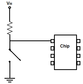
A pull up resistor pulls a pin of a chip up to a HIGH state, so that it is normally HIGH unless intentionally brought LOW.
The perfect model of a pull-up resistor circuit is shown below.

This pull up resistor circuit can be used exactly as is for every pull up resistor circuit.
The pin of this chip will be HIGH normally and when the switch is closed drops to LOW.
How this circuit works is the resistor is directly connected to the positive voltage. Due to the open switch, all of the voltage from the power supply drops across the resistor.
When the switch is closed, now the pin makes direct contact with ground and is now LOW.
Pull Down Resistor Circuit
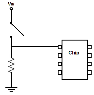
A pull down resistor pulls a pin of a chip down to a LOW state, so that it is normally LOW unless intentionally brought HIGH.
The perfect model of a pull-down resistor circuit is shown below.

This pull down resistor circuit can be used exactly as is for every pull down resistor circuit.
The pin of this chip will be LOW normally and when the switch is closed becomes HIGH.
How this circuit works is the pin of the chip, when the switch is open, is connected directly to ground. Therefore, it is at a logic LOW level. When the switch is closed,
the voltage from the power supply falls across the resistor. Thus, the pin of the chip is drawn to a HIGH state.
Related Resources
How to Connect a Pull Up Resistor
How to Connect a Pull Down Resistor