
Silicon-controlled Rectifier (SCR) Specifications- Explained
There are many different specifications which you'll find on a datsheet for silicon-controlled rectifiers (SCRs).
There is gate trigger voltage, gate trigger current, holding current, on-state voltage, peak gate power dissipation...
What do all of these terms mean? How do they apply to the SCR? Why are they important? What significance do they hold when choosing an SCR for a circuit?
We hope to explain these terms so that you can understand the specifications of an SCR.
SCR Datasheet Specifications
Gate Trigger Current
Gate Trigger Voltage
Holding Current
On-state Voltage
Peak Gate Power Dissipation
Gate Trigger Current
Gate Trigger Current is the minimum gate current needed to switch the SCR on.
Just like a BJT, an SCR needs sufficient current applied to its gate terminal in order to turn on.
Gate Trigger Voltage
Gate Trigger Voltage is the minimum gate voltage required to
trigger the gate terminal, which then turns on the SCR.
Holding Current
Holding Current is the minimum current through the anode-to-cathode terminal required to maintain the SCR's on state.
While the gate trigger current is the current needed to switch the SCR to the on state, the holding
current is the current required to maintain this on state.
On-state Voltage
On State-Voltage is the anode-to-cathode voltage present when the SCR is on.
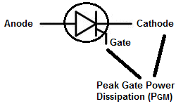
Peak Gate Power Dissipation
The Peak Gate Power Dissipation is the maximum power that may be dissipated between the gate and the cathode region
in a silicon-controlled rectifier (SCR).
Related Resources
How to Build a Very Basic SCR Circuit