
How to Build a Speaker Crossover Network Circuit
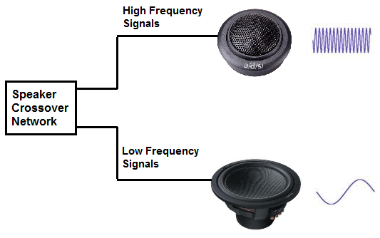
In this project, we build a speaker crossover network. A Speaker Crossover Network is a network that filters input audio sound signals by frequency, diverting low-frequency sounds to a woofer and high-frequency sounds to a tweeter.
The reason we form a network of these different speakers is because different speakers play different sounds better than others. We incorporate these 2 speakers to play the best possible quality audio we can. A woofer is a speaker that plays out low-frequency (bass) sounds with great audio quality. A tweeter would play out bass poorly. However, it plays out high frequency sounds with great quality. (Many times, too, a midrange speaker is added to play out midrange frequencies. However, for simplicity, we omit midrange speakers in this project.) To get a good speaker system, it's best to incorporate a woofer and tweeter together so that you get the best audio from the full audio spectrum, which is from 20 to 20,000Hz.
We use 2 components to form this speaker crossover network- a single inductor and a single capacitor. An inductor is a component that has high reactance at high frequencies. Therefore, it blocks high-frequency signals and diverts it through the capacitor to the tweeter. A capacitor is a component that has high reactance at low frequncies. It blocks low-frequency signals from passing through and diverts it through the inductor to the woofer. This is how we form our speaker crossover network.
This project serves to teach you about woofers and tweeters, and how they can be incorporated into a network to get the best possible sound.
Components
- Tweeter
- Woofer
- 39μF electrolytic capacitor
- 2.55mH Inductor
If you can't find the exact values for the inductor and capacitor, you can use one that is as close as possible to these values.
Speaker Crossover Network Circuit
The speaker crossover network we will build to divert low-frequency sounds to a woofer and high-frequency sounds to a tweeter is shown below.
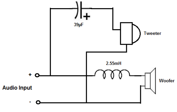
The circuit operates on the principle of filtering systems. The input audio signals that enter the circuit are filtered by the inductor and capacitor network.
A capacitor is a device that has high reactance at low frequencies and low reactance at high frequencies. This means that a capacitor doesn’t allow low-frequency signals to pass through it but allows high-frequency signals to do so. This is how a capacitor diverts the high-frequency sounds to the tweeter.
The capacitor reactance formula is XC= 1 / (2πfC), where f is the frequency of the audio signal and C is the capacitance of the capacitor. You can see that, based on this formula, that the smaller in value the frequency is, the greater in value the rectance is. The larger in value the frequency, the smaller in value the reactance is.
An inductor is a reactive device just like a capacitor but has the opposite reactive effect. An inductor has high reactance at high frequencies and low reactance at low frequencies. This means that an inductor doesn’t allow high-frequency signals to pass through it but allows low-frequency signals to do so. This is how an inductor diverts the low-frequency sounds to the woofer. When you have this type of network, it forms a speaker crossover network. Woofers can play out low-frequency sounds (bass) very well, and tweeters play out high-frequency sounds very well. Thus, you can incorporate a much better speaker system if you have these 2 speakers connected in a system rather than just a single general speaker.
The inductor reactance formula is XC= 2πfL, where f is the frequency of the audio signal and L is the inductance of the inductor. You can see that, based on this formula, that the greater in value the frequency is, the greater in value the rectance is. The smaller in value the frequency is, the smaller in value the reactance is.
And this is how a very basic speaker crossover network circuit works.
Related Resources
How to Build a Simple Speaker Circuit
How to Build a Speaker Circuit with Adjustable Volume