How to Connect a TLC5940 PWM Driver to an Arduino
In this project, we will show how to connect an TLC5940 PWM driver chip to an arduino microcontroller.
A PWM driver chip is a chip that allows for additional PWM output pins.
On arduino microcontrollers, there are only a few PWM output pins. There may be 6 or so depending on the arduino board in use. For the arduino uno, there are 6 PWM pins.
So if more PWM pins are needed, you can always use a PWM driver chip.
The TLC5940 allows for an additional 16 PWM pins, which is very significant.
In case you are wondering exactly what PWM is or what a PWM pin is, we'll now give a brief overview.
PWM stands for Pulse Width Modulation. It's a way of getting analog output results through digital means.
PWM functions as if we're sending out an analog signal. So the device that receives can get any voltage from +VCC (e.g. 5V) to GND, which is 0.
We do this through a digital signal varying the length of time that the signal is on.
Let's start with the most basic examples first. This should be easy to get.
Let's say we send a 0V signal the whole time to a device, so that the signal sent is as shown below.
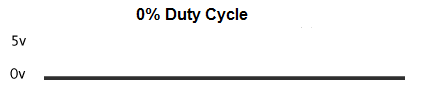
This means that the signal sent to the device is always LOW (0V). If the device is an active HIGH device, it will always be off.
The duty cycle which is the period of time that a signal is HIGH is 0, since in this case, it's never HIGH. It's always LOW. Therefore, it's a 0% duty cycle.
The function we use for PWM signals in arduino code is the analogWrite() function, which is the same function we use for analog pins. Remember that PWM mimics analog pins do, so they both use the same function. The analogWrite() function varies in value from 0 (lowest value) to 255 (highest value). So 0 means fully off, while 255 means fully on.
For a signal where the signal is always LOW, this equals, analogWrite(0). This is also the same as a digitalWrite(pin, LOW).
A second example is that we send a 5V signal the whole time to a device, so that the signal sent is as shown below.
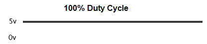
This means that the signal sent to the device is always HIGH (5V). If the device is an active HIGH device, it will always be on.
The duty cycle, in this case, is 100%, since in this case, it's always HIGH (always ON).
For a 100% duty cycle, the value of the analogWrite function would be, analogWrite(255).
This is also the equivalent of the digitalWrite() function value, digitalWrite (pin, HIGH).
Now, as a third example, we show a signal that gets a 5V signal half of the time and a 0V signal half of the time,
and the 2 alternate back and forth.
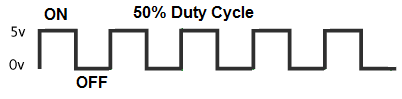
So this replicates ON-OFF, ON-OFF, ON-OFF.
So if sent to an LED, the LED will flicker on half of the time and off half of the time. If sent to motor device, it will create lower speeds than if a 100% duty cycle signal was sent to it.
A 50% duty cycle is represented by the analogWrite() function value, analogWrite(127). Since the analogWrite() function varies from 0 to 255, a 50% duty cycle is 255/2≈ 127.
And the essence of PWM is that we can have PWM signals of any duty cycle from 0% to 100% or any analogWrite() value from 0 to 255.
To convert a duty cycle value to an analogWrite() value, you use the formula:
(Duty Cycle/100) * 255
So if you want a duty cycle of 40%, the analogWrite() value would be 102, analogWrite(102).
Pulse Width Modulation (PWM) is great for turning devices on and off for different lengths of time (essentially flickering devices on and off) and controlling the speed of motors (a lower duty cycle equals a much lower speed).
Now that we've reviewed PWM, let's go back to our circuit of connecting a TLC5940 PWM driver chip to an arduino
microcontroller.
Components
- TLC5940 PWM Driver Chip
- 2KΩ resistor
- 5 LEDs
- Arduino microcontroller
The TLC5940 PWM driver chip can be obtained for under $1 on ebay.
It is a 28-pin chip.
The datasheet for this chip can be found at the following link: TLC5940 Datasheet.
The pinout of the TLC5940 is shown below.
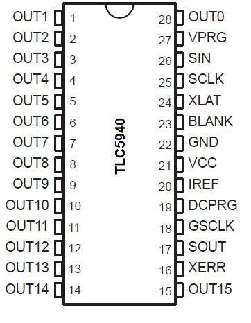
The TLC5940 can be powered with +5V. Therefore, we can connect VCC to +5V. We connect GND to ground. This completes the powering that's necessary.
The PWM output pins of the chip are OUT1-OUT15, which are the 16 PWM pins. To these we connect output devices such as LEDs.
The TLC5940 needs a clock pin. This is the SCLK pin. We connect the arduino clock signal from digital pin 13 to the SCLK pin of the TLC5940, which is pin 25.
The SIN pin is the serial data input pin. It's how data gets transferred from the microcontroller into the TLC5940.
The SOUT pin is the serial data output pin. It's how data is transferred from the TLC5940 to the microcontroller.
The BLANK pin blanks all outputs when HIGH. When LOW, the blank feature is disabled.
The DCPRG pin is the Switch DC data input pin. When LOW, it is connected to the default EEPROM value of 63. If tied HIGH, it requires much more complex programming. To avoid this, it should be simply tied LOW.
The GSCLK is the reference clock for grayscale PWM control. We connect this to a PWM digital pin. We connect it to digial pin 3 on the arduino.
The IREF pin is the reference current terminal. This sets the maximum current that can flow out of the output pins. Imax is calculated by the formula, Imax= 1.24V/RIREF * 31.5. Imax must be set between 5mA and 120mA. This value of current is controlled by an external resistor placed between the IREF pin and GND. You may have to consider the current needed by the device you're powering when calculating what resistor should be placed between IREF and GND. In the case of this circuit, we're powering which need about 20mA of current roughly. So putting 20mA in the formula just mentioned, we get roughly 1953Ω. This is roughly 2KΩ. So we place a 2KΩ resistor between IREF and GND, since we want a current of 20mA to power our load devices attached to the output pins. This current is common for all of the output devices. If you want to adjust the current coming out of an individual, you do so via external methods, such as adding another resistor to lower current or a transistor to increase current. But this current affects all the currents out of the output pins. So they will all be what you set it to via this resistor.
The VPRG pin is the just a pin, along with DCPRG, that sets the operation mode of the TLC5940 chip. When DCPRG is LOW and VPRG is connected to GND, the chip is operating the chip is operating in Grayscale PWM Mode. The other 2 modes are Dot Correction Data Input Mode and EEPROM Programming Mode. The Dot Correction is a more sophisticated mode which allows for the capability to fine adjust the output current of each channel OUT0 to OUT15 independently, so that each output channel can output its own current. Each of the 16 channels can be programmed with a 6-bit word. The Dot Correction mode allows for greater flexibility if we need different currents from each of the output channels but requires a greater deal more of programming. The Grayscale PWM mode is probably the simplest and it's the one we will use in this circuit.
The XERR pin is the error output pin. We leave this pin unconnected.
The XLAT pin is the level triggered latch signal. When HIGH, the TLC5940 writes
the data in the input shift register to DC register. When LOW, the TLC5940 holds the data in the DC
register. Therefore, this pin has to go HIGH in order for data transfer to occur.
TLC5940 PWM Driver Circuit with an Arduino Microcontroller
The TLC5940 PWM driver circuit we will build with
an arduino microcontroller is shown below.
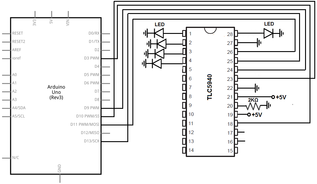
We will now explain the hardware connections.
First to connect power, we connect VCC to the +5V terminal of the arduino and the GND pin to the GND terminal of the arduino.
We connect an LED to the first 5 output pins, OUT0 to OUT4. If you want, you can LEDs to the rest of the output pins. But for the sake of simplicity, we will just show how to turn on and off 5 pins.
We connect VPRG, pin 27, to ground and DCPRG, pin 19. to VCC. When VPRG is grounded and DCPRG is HIGH, the TLC5940 is in Grayscale PWM mode, which is the moe we want to operate in.
We connect the SIN (Serial Data Input) pin, pin 26, to digital pin 11 on the arduino. This is how the arduino sends data to the TLC5940. When we're programming to decide which pins turn on or off, this the line used to do so, the line used to send data to turn pins attached to the output pins of the TLC5940 on and off.
We connect the SCLK pin, pin 25, to the digital clock pin, pin 13, on the arduino. The TLC5940 clocks data from the SIN pin to its internal register on the rising edge of the SCLK clock signal.
We connect the XLAT pin, pin 24, to digital pin 9 on the arduino. The XLAT pin is the pin that once data is clocked in from the serial data input pin to the internal registers, it has to be latched in by the XLAT being HIGH. If the XLAT pin is LOW< data cannot be latched in into the internal registers. so the XLAT pin is really the latch pin. It latches data from the serial data input pin to the internal registers of the TLC5940.
We connect the BLANK pin, pin 23, to digital pin 9 on the arduino. This allows us to clear all outputs, if wanted.
We connect the IREF pin, pin to a 2KΩ connected to ground. This sets the current output by all the output pins of the TLC5940. Since we're lighting LEDs, which need about 20mA in order to work, the 2KΩ resistor gives about this amount of current.
The GSCLK pin, pin 18, connects to digital pin 3 on the arduino. After the first GSCLK goes HIGH, OUT0 can turn on. Then after the second GSCLK goes HIGH, OUT1 can turn on, and so on and so forth.
The SOUT (Serial Data Output) pin, pin 17, is left unconnected. This is because the arduino sends data to the TLC5940 chip via the SIN pin, but the arduino does not need to receive data from the TLC5940. It's really one-way communication. The arduino simply needs to send data, without receiving any, for the circuit to work.
The XERR pin, pin 16, is left unconnected. We are not keeping track of errors.
Code
The code to turn on the 5 LEDs attached to the first 5 output pins of the TLC5940 PWM driver chip is shown below.
#include <TLC5940.h>
void setup()
{
Tlc.init(0);
}
void loop()
{
Tlc.set(0, 4095);
Tlc.set(1, 4095);
Tlc.set(2, 4095);
Tlc.set(3, 4095);
Tlc.set(4, 4095);
Tlc.update();
}
The first block of code imports the TLC5940 library. This is necessary in order to use the functions in the code.
After this, in our setup() function, we call the function Tlc.init(0). This can be seen as an initialization function. It's kind of like the boot start for the program. The Tlc.init() function accepts an optional parameter of value 0 to 4095. With a value of 0, all the LEDs will be off. With a value of 4095, the LEDS will be at their brightest level. In this program, we start them off all at 0. But you have the ability to start them off at any level.
Next we have our loop() function. In this funtcion, we use the Tlc.set() function in order to turn pins on or off and to what level. The Tlc.set() functions accepts 2 parameters. These are: Tlc.set(channel, level) where channel is output pin from 0 to 15 and the level is the level of brightness for that channel from 0 to 4095. In this program we set the levels on all 5 LEDs we turn on to the brighest level, which is 4095. The last part of the loop is the Tlc.update() function. Basically, we the output values but then after that, we have to actually update the program so that these values are written into the TLC5940. You set the values and then you have to latch it. The Tlc.update() function can be thought of as the latching part of it.
And this is our program. Again, you can set any brightness you want. You can fade in and out LEDs by writing for loop functions, such as, for(int i=0; i < 4095; i++){ Tlc.set(0, i); } and then use the for loop, for (int i=4095; i > 0; i--) { Tlc.set(0,i) }. These for loops will gradually turn an off LED brighter and brighter to its brightest level at 4095 and then gradually make it dimmer and dimmer until the LED is off.
There are many different methods, but this is how a PWM driver chip can be connected and programmed to an arduino
microcontroller.
>
Related Resources
How to Build a 74HC238 3-to-8 Decoder Circuit with Manual Pushbuttons